CV
-
100/
P1100 Series | User Manual
18
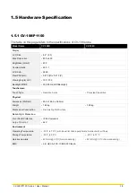
1.5 Hardware Specification
1.5.1 CV-108/P1100
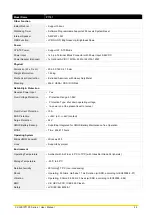
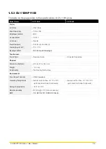
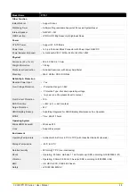
The table on this page refers to the specifications of CV-108 alone
Model Name
CV-108R
CV-108C
Display
LCD Size
• 8.4" (4:3)
Max. Resolution
• 800 x 600
Brightness( cd/m2)
• 400
Contract Ratio
• 600 : 1
LCD Color
• 262K
Pixel Pitch(mm)
• 0.213 (H) x 0.213 (V)
Viewing Angle( H-V)
• 150 / 130
Backlight MTBF
• 30,000 hrs(LED Backlight)
Touchscreen
Touch Type
•
Resistive 5-wire
•
Projected Capacitive
Physical
Dimension (WxDxH)
• 262 x 186.2 x 56.2mm
Weight
• 1.62kg
• 1.58kg
Mechanical Construction
•
Die-Casting Flat Surface
Reliability & Protection
Front Panel Protection
• IP 65 Compliant
Surge Protection
• 2kV
Environment
Operating Temperature
•
-20°C to 70°C (with Industrial Grade peripherals; Ambient with air flow)
Storage Temperature
•
-30°C to 80°C
•
-20°C to 70°C
Relative Humidity
•
80% RH @ 50°C (Non-condensing)
•
85% RH @ 50°C (Non-condensing)
EMC
• CE, UKCA, FCC, ICES-003 Class A
Summary of Contents for CV-100/P1100 Series
Page 15: ...CV 100 P1100 Series User Manual 15 Chapter 1 Product Introductions ...
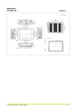
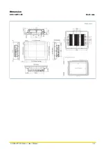
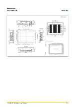
Page 21: ...CV 100 P1100 Series User Manual 21 Dimension CV 108 P1101 Unit mm ...
Page 25: ...CV 100 P1100 Series User Manual 25 Dimension CV 110 P1101 Unit mm ...
Page 29: ...CV 100 P1100 Series User Manual 29 Dimension CV 110H P1101 Unit mm ...
Page 33: ...CV 100 P1100 Series User Manual 33 Dimension CV 112H P1101 Unit mm ...
Page 37: ...CV 100 P1100 Series User Manual 37 Dimension CV 115 P1101 Unit mm ...
Page 41: ...CV 100 P1100 Series User Manual 41 Dimension CV W115 P1101 Unit mm ...
Page 45: ...CV 100 P1100 Series User Manual 45 Dimension CV 117 P1101 Unit mm ...
Page 49: ...CV 100 P1100 Series User Manual 49 Dimension CV 119 P1101 Unit mm ...
Page 53: ...CV 100 P1100 Series User Manual 53 Dimension CV W121 P1101 Unit mm ...
Page 57: ...CV 100 P1100 Series User Manual 57 Dimension CV W124 P1101 Unit mm ...
Page 61: ...CV 100 P1100 Series User Manual 61 Chapter 2 Switches Connectors ...
Page 62: ...CV 100 P1100 Series User Manual 62 2 1 Location of Switches and Connectors 2 1 1 Top View ...
Page 63: ...CV 100 P1100 Series User Manual 63 2 1 2 Bottom View ...
Page 71: ...CV 100 P1100 Series User Manual 71 Chapter 3 System Setup ...
Page 87: ...CV 100 P1100 Series User Manual 87 ...
Page 89: ...CV 100 P1100 Series User Manual 89 Chapter 4 BIOS Setup ...
Page 107: ...CV 100 P1100 Series User Manual 107 Chapter 5 Product Application ...


