Document: Service Manual
Description: Treadmill
Model: M7 LED
Page: 54 of 60
54
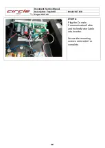
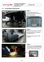
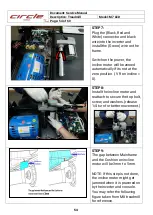
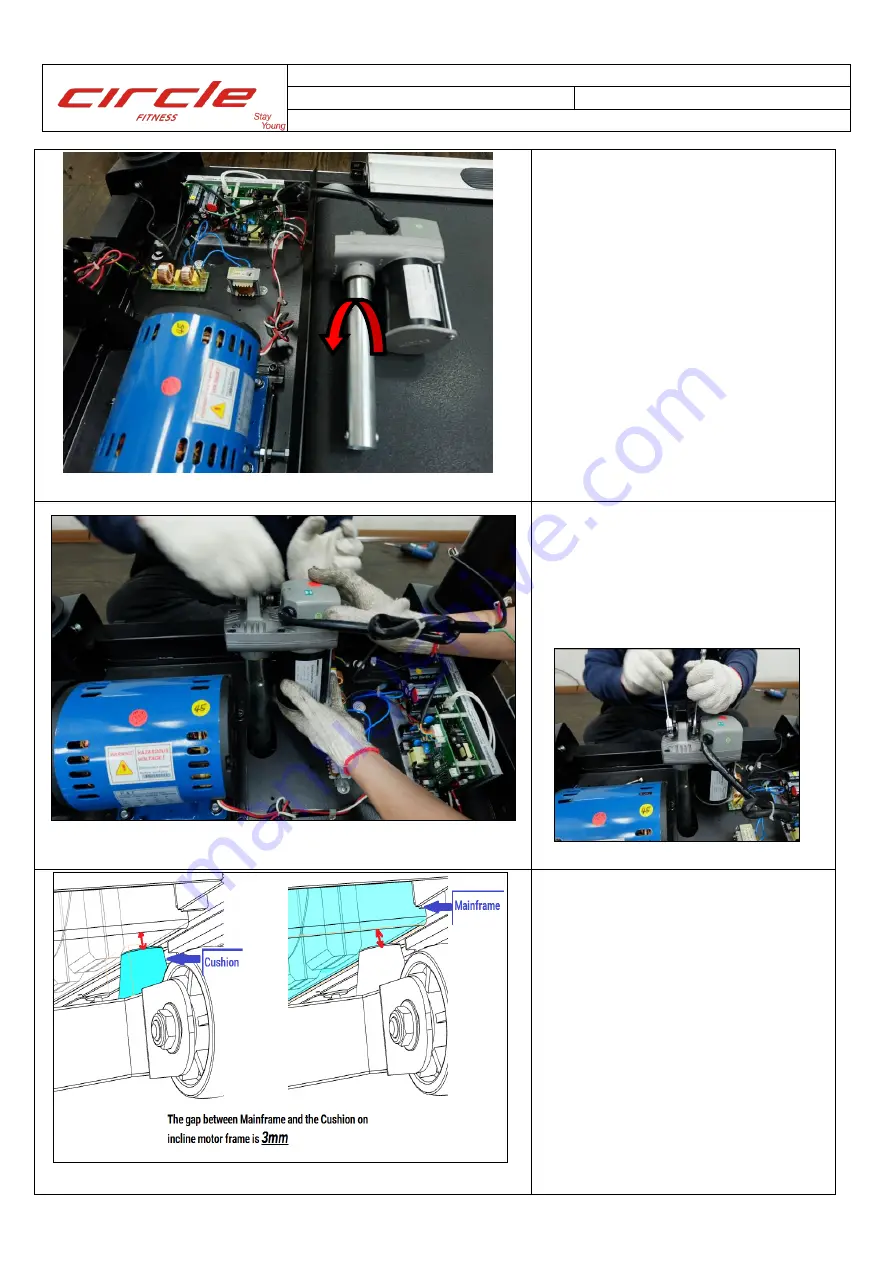
STEP7:
Plug the (Black, Red and
White) connector and black
wire into the inverter and
install the (Green) wire on the
frame.
Switch on the power, the
incline motor will be zeroed
automatically if its not at the
zero position. ( VR on incline =
0).
STEP8:
Install the incline motor and
reattach to secure the top bolt,
screw, and washers.(release
1/4 turn for better movement.)
STEP9:
The gap between Mainframe
and the Cushion on incline
motor will be 3mm to 5mm.
NOTE: If this step is not done,
the incline motor might get
jammed when it is powered on
by the inverter and console.
You may refer the following
figure taken from M8 treadmill
for reference.
Summary of Contents for M7
Page 1: ......

