06
Raption 150 Series Installation Manual
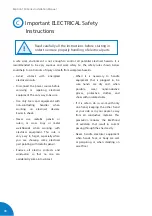
The Charge Point is designed for installation at indoor and outdoor areas. For
each of the different conditions of installation, the unit must be installed safely
and ensure adequate protection.
• Charge point must not be
installed in areas where there is
potential risk of explosions.
• Do not install the Charge Point
where falling objects may
damage the equipment.
• The surface where the Charge
Point is placed must withstand
the mechanical forces.
• Do not use this unit for anything
other than electric vehicle
charging modes are expected in
IEC 61851-23.
• Do not modify this unit. If
modified, CIRCONTROL will
reject all responsibility and the
warranty will be void.
• Comply strictly with electrical
safety regulations according to
your country.
• Do not make repairs or
manipulations with the unit
energized.
• Only trained and qualified
personnel should have access
to the electrical parts inside the
Charge Point.
• Check the installation annually
by qualified technician. Follow
Service Manual Instructions.
• Remove from service any item
that has a fault that could be
dangerous for users (broken
plugs, caps that don’t close...).
• Use only Circontrol supplied
spare parts.
• Do not use this unit if the
enclosure or the EV connector is
broken, cracked, open, or shows
any other indication of damage.
2
Read carefully all the instructions before starting in
order to ensure properly installation of the charge
point.
A
Important safety instructions
Summary of Contents for Raption 150 Series
Page 1: ...Installation Manual Raption 150 Series ...
Page 2: ......
Page 4: ......
Page 7: ...03 ...
Page 20: ...16 Raption 150 Series Installation Manual Power Unit front door Power input supply ...
Page 21: ...17 Power Unit rear door Output wiring to Dispenser ...
Page 27: ...23 1 2 3 4 ...
Page 34: ...30 Raption 150 Series Installation Manual E Dispenser template dimensions 435 300 70 ...
Page 35: ...31 400 165 280 310 ...
Page 37: ...33 0 1920 ...
Page 51: ...47 CCS CCS CHA CHA 3 ...
Page 53: ...49 PE DC 2 L N PE ETHERNET CABLE 2 1 3 DC 1 2 2 Wiring connection for the Dispenser Scheme ...
Page 55: ...51 L1 N PE ETHERNET 1 2 ...
Page 56: ...52 Raption 150 Series Installation Manual CCS CCS 3 ...
Page 57: ...53 CHA PE CHA 3 ...
Page 59: ...55 ...
Page 65: ...61 ...


