40
Raption 150 Series Installation Manual
5
Regardless of the electrical characteristics of the power line, be sure to supply to the
Charge Point with the necessary electrical features indicated at the unit characteristics
label, understood as, supply voltage, grid frequency and required apparent power. In
the case that the power line characteristics are different from those required, must do
the necessary adaptation of the same to meet this requirement.
The Charge Point has internal electrical protections in each socket-outlet for the
protection of the user against an electrical failure, according to the international
standard IEC 61851-1:2017. In order to guarantee the total protection of the users
and the installation (power supply line included) in front of any electrical hazard, it is
mandatory to install a main circuit breaker (MCB) and a residual current device (RCD)
upstream of the charger. These electrical protections and the rest of the installation
have to be aligned with the local and national rules and the selectivity of the protections
has to be guaranteed at all times.
The proper earthing system must be TT or TN-S. The ground loop impedance
measurement for the entire installation must be less than 80 ohms. The earth
resistance of the charging point could be less if required by national regulations. It
is recommended to maintain these conditions over the years, therefore, technically
competent personnel will carry out the verification of the installation of grounding, at
least once a year, at the time when the terrain is drier.
Before starting wiring connection for the Charge Point, have to be checked the
following important elements:
•
After unpacking the Charge Point, ensure that all electrical components are in
good condition.
•
It is recommended to strictly follow the current regulations to determine the
appropriate section of the power cables to feed the Charge Point and at any time
as a minimum comply with indicated in the Technical Data here below.
•
Make sure the switch (MCCB or fuses) from the main electrical panel from the
installation are cutting the electricity supply during Charge Point installation.
•
After the installation, you must seal all holes inside the Charge Point to prevent
access of dirt, foreign objects, animals, etc.
Summary of Contents for Raption 150 Series
Page 1: ...Installation Manual Raption 150 Series ...
Page 2: ......
Page 4: ......
Page 7: ...03 ...
Page 20: ...16 Raption 150 Series Installation Manual Power Unit front door Power input supply ...
Page 21: ...17 Power Unit rear door Output wiring to Dispenser ...
Page 27: ...23 1 2 3 4 ...
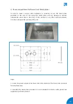
Page 34: ...30 Raption 150 Series Installation Manual E Dispenser template dimensions 435 300 70 ...
Page 35: ...31 400 165 280 310 ...
Page 37: ...33 0 1920 ...
Page 51: ...47 CCS CCS CHA CHA 3 ...
Page 53: ...49 PE DC 2 L N PE ETHERNET CABLE 2 1 3 DC 1 2 2 Wiring connection for the Dispenser Scheme ...
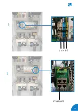
Page 55: ...51 L1 N PE ETHERNET 1 2 ...
Page 56: ...52 Raption 150 Series Installation Manual CCS CCS 3 ...
Page 57: ...53 CHA PE CHA 3 ...
Page 59: ...55 ...
Page 65: ...61 ...


