Einbau- und Betriebsanleitung
Installation and Operating instructions
Instructions de montage et de service
6139-8010
07/2018
Thank you for purchasing this RTK product. Each product is thoroughly inspected following production to provide you with the highest level quality. To ensure
you will be able to utilise this product to its full capacity we strongly advise users to carefully read the operator’s manua
l.
•
The operator’s manual
should be included in the delivery to the customer.
•
The operator’s manual
is subject to change or review without prior notice. Changes in the product specification, product structure and/or the product
components will not necessarily result in a modification of the operator’s manual
.
•
Do not copy or reproduce the operator’s manual
for any purpose without the approval of Regeltechnik Kornwestheim GmbH.
2 Manufacturer warranty
•
To ensure safety always follow the instructions contained in the operator’s manual
. The manufacturer assumes no liability for damages due to failure
to follow instructions.
•
The manufacturer is not liable for damages or accidents caused by a modification of the product or its components. In the event a modification is
required, please contact the manufacturer directly.
•
Improper use will void the warranty
•
For detailed warranty information please contact Regeltechnik Kornwestheim GmbH directly.
3
Product description
3.1
Main features and functionalities
4
Developed for high performance and robustness. Suitable for use in high vibration environments.
5
Robustness proven with at least 1 million test cycles.
6
Reaction time is very small and accurate
7
Adjustment of ½ split range through simple parts exchange
8
Low air consumption for efficiency
9
Easy to adjust direct / reverse action.
10
Easy to adjust zero and stroke width
11
Easy to implement feedback connection
3.2
Functionality
<Figure1>
If the supply pressure rises the flapper (2) moves the jet (3), increasing the space between the jet (3) and the flapper (2) resulting compressed air escaping from
the upper spool (5). This in turn causes a downward movement of the spool (5). If the spool moves upward the actuator (10) is supplied with compressed air. The
increase in pressure causes the drive screw (12) to move. The movement is transferred to the cam (14), creating traction on the stroke width spring (16). The
traction of the stroke width spring (16) is compensated by the lift drive. This moves the flapper (2) into its normal position, minimising the space between the jet (3).
When the air pressure drops at the jet outlets (3) the pressure again increases at the spool (5). The spool (5) would return to its normal position and attempt to
block its position (7), which would break the compressed air supply for the drive (10). If the drive (10) adjusts the motion the positioner returns to its regular position.
3.3 Nameplate specifications
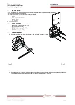
Sup p ly
Out 2
Out 1


