4
WARNING
When inspecting/servicing the shaft seal and/or bearing, the power rotor with these
components installed can be removed as a subassembly. If for any reason the pump is
disassembled further than this, it is possible the idler rotor balance piston housings
(20) may fall off. The idler rotor balance piston housings MUST be properly in place at
reassembly. If idler rotor balance piston housings are not properly installed on the idler
rotors, the pump WILL experience catastrophic failure.
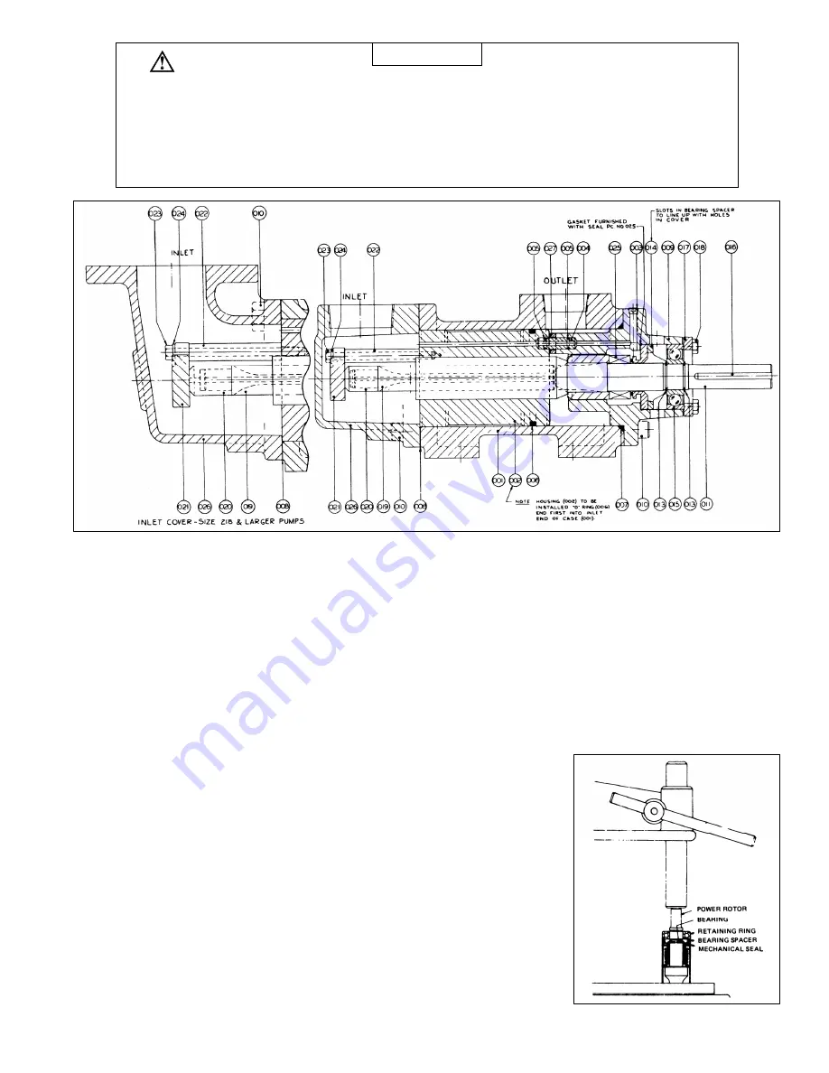
Assembly Drawing
DISASSEMBLY OF BEARING AND MECHANICAL SHAFT SEAL
1. Remove the power rotor assembly.
Power rotor assembly consists of power rotor, bearing, bearing spacer, retaining rings and mechanical seal.
a. Remove coupling or sheave.
b. Remove hex bolts (18).
c. Remove bearing retainer (17).
d. Pull power rotor assembly out of pump case.
2. Remove the outer retaining ring from the power rotor with a screwdriver (13).
3. Remove the inner retaining ring from its groove by pulling back
the mechanical seal and prying with a screwdriver (13).
4. Press the bearing, spacer and stationary seat off the power rotor
(Figure 1).
5. Remove seal subassembly (Figure 3) and gasket from under the
stationary seat.
6. Inspect the shaft. If the shaft is pitted or badly scratched or the
retaining ring grooves damaged, replace the power rotor.
7. Discard the old seal, bearing and retaining rings.
Figure 1


