background image

– 12 –

 Apply the test leads to the resistor being measured. If the resistor is part 

of a circuit, it is necessary to disconnect one end of the resistor to avoid 

any unwanted interference from the rest of the circuit.

 Read the displayed resistance.

NOTE:
• ‘I’ is also displayed when the inputs are not connected. 
• When measuring resistance above 1M  , the meter may take a few seconds to get 

a stable reading. 

• Never measure a resistor that has voltage on it.

6. CONTINUITY TEST


WARNING: 

NEVER CONNECT THE TEST LEADS TO ANY VOLTAGE WHEN THE FUNC-

TION SWITCH IS SET TO 

/

. REMOVE ALL POWER FROM THE CIRCUIT BEING TESTED 

WHEN CHECKING RESISTANCE. DISCHARGE ANY CHARGED CAPACITORS. 

 Set the function switch to 

/

.

 The LED next to  V/ /F/ /  jack will turn on. 

 Plug the red test lead into  V/ /F/ /  jack and 

the black test lead into 

 jack.

 Apply the test leads to the circuit.

 The buzzer will sound if the 

resistance is less than 30  and the 

measured resistance value will be 

displayed in ohms.

CAP

CIRCUIT-TEST

DMR-4200

20A

TEMP

mA

HOLD

POWER

CAT II 1000V

V/Ω/F/   /

COM

D

C

 V

O

LT

S


OHMS 

Ω

C

A

PA

C

IT

A

N

CE

AC

 V

O

LT

S

AC AMPS

D

C A

M

PS

TEMP F

REQ

WIRE

Summary of Contents for DMR-4200

Page 1: ...USER S MANUAL DIGITAL MULTIMETER DMR 4200 CIRCUIT TEST ELECTRONICS www circuittest com...

Page 2: ......

Page 3: ...ent 8 3 DC Current Measurement 8 10 a less than 200mA DC current b 200mA or more DC current 4 AC Current Measurement 10 11 a less than 200mA DC current b 200mA or more AC current 5 Resistance Measurem...

Page 4: ...C RMS as these volt ages pose a shock hazard Always consider circuits to be energized Never assume any equipment to be de energized Always start with power off Set the function switch to the correct s...

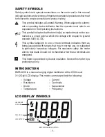
Page 5: ...with respect to ground exceeds 500V AC DC This symbol adjacent to one or more terminals indicates them as being associated with ranges that may in normal use be subjected to particularly hazardous vo...

Page 6: ...st Lead Input Indicating LEDs Lighted LED indicates the correct jack to plug in the test lead for the selected function LED will turn off after the test lead is fully inserted If the test lead is inco...

Page 7: ...rent of 1 0 mA maximum Continuity Audible signal sounds if resistance is less than 30 Over range indication I is displayed Operating Temp 41 to 95 F 5 to 35 C Storage Temp 14 to 122 F 10 to 50 C Relat...

Page 8: ...ading 1 digit 2 0 reading 5 digits AC CURRENT AC A 40 400HZ 2mA 200mA 20A 1 A 100 A 10mA 1 0 reading 3 digits 1 8 reading 3 digits 3 0 reading 7 digits RESISTANCE 200 2k 20k 200k 2M 20M 0 1 1 10 100 1...

Page 9: ...REOFTHEVOLTAGE BEING MEASURED SELECT THE HIGHEST RANGE AND REDUCE UNTIL A SATISFACTORY READING IS OBTAINED Set the function switch to 1000 on the DC VOLTS scale The LED next to V F jack will turn on P...

Page 10: ...yed voltage If the reading displayed does not have a suf cient number of digits i e 002 instead of 2 1011 set the function switch to the next lower range Repeat until you have maximum digits possible...

Page 11: ...Current Measurement CAUTION Do not exceed 15 seconds when measuring the 20A range and wait for 30 minutes between each measurement Set the function switch to 20 on the DC Amps scale The LED above 20A...

Page 12: ...OBTAINED a Less than 200mA AC Current Measurement Set the function switch to 200m on the AC AMPS scale The LED next to TEMP mA jack will turn on Plug the red test lead in TEMP mA jack and the black t...

Page 13: ...to the meter 5 RESISTANCE MEASUREMENT WARNING NEVER CONNECT THE TEST LEAD TO ANY VOLTAGE WHEN THE FUNCTION SWITCH IS SET TO REMOVE ALL POWER FROM THE CIRCUIT BEING TESTED WHEN CHECK ING RESISTANCE DIS...

Page 14: ...ITY TEST WARNING NEVER CONNECT THE TEST LEADS TOANY VOLTAGE WHEN THE FUNC TION SWITCH IS SET TO REMOVE ALL POWER FROM THE CIRCUIT BEING TESTED WHEN CHECKING RESISTANCE DISCHARGE ANY CHARGED CAPACITORS...

Page 15: ...into V F jack and the black test lead into jack Apply the test leads across the diode terminals and note the meter reading Reverse the diode and note this reading Based on the reading the result can...

Page 16: ...ocouple adapter model no TL 340 are required Set the function switch to TEMP The LED next to TEMP mA jack will turn on Observing the polarity plug in the temperature probe adapter with inserted in TEM...

Page 17: ...I appears on the display the value of the capacitor is over the maximum range of the meter 11 HOLD FUNCTION This function is used to hold a reading When this pushbutton is pressed the data being disp...

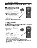
Page 18: ...FUSE REPLACEMENT WARNING DISCONNECT BOTH TEST LEADS FROM ANY SOURCE OF VOLTAGE BEFORE REMOVING THE BACK COVER DO NOT OPERATE THE METER UNTIL THE BACK COVER IS IN PLACE AND FASTENED SECURELY a 0 5 Amp...

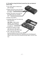
Page 19: ...open Remove the batteries Carefully lift the top of the case away from the bottom CAUTION Lift the top case carefully do not break the wires attached to the battery compartment Gently lift the battery...

Page 20: ...couple Adapter TL 340 Test Leads with Screw on Alligator Clips TL 222 LIMITED WARRANTY Circuit Test Electronics warrants to the original purchaser that this product be free of defect in material or wo...

Reviews: