– 14 –
8.
FREQUENCY MEASUREMENT
WARNING:
NEVER MEASURE FREQUENCY ON A CIRCUIT
WITH MORE THAN 250V.
➔
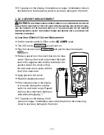
Set the function switch to
FREQ
.
➔
The LED next to
V/ /F/ /
jack will turn on.
➔
Plug the red test lead in
V/ /F/ /
jack and black test
lead in
jack.
➔
Apply the test leads to the point of
measurement.
➔
Read the displayed frequency.
9. TEMPERATURE MEASUREMENT
WARNING:
REMOVE ALL VOLTAGE SOURCES FROM THE CIRCUIT TO BE TESTED
BEFORE TAKING A TEMPERATURE MEASUREMENT. DO NOT MEASURE TEMPERATURE OF
METAL PARTS WITH A VOLTAGE ON THEM.
NOTE: To measure temperature, ‘K’ Type Thermocouple (model no. TL-190) and
Thermocouple adapter (model no. TL-340) are required.
➔
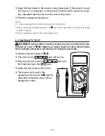
Set the function switch to
TEMP
.
➔
The LED next to TEMP/mA jack will turn on.
➔
Observing the polarity, plug in the temperature
probe adapter with + inserted in TEMP/mA
jack and – in
jack.
➔
Plug the ʻKʼ type thermocouple in this adapter.
➔
Touch the probe tip to the component you are
testing and keep it there for about 30 seconds or
until the reading stabilizes.
➔
The digital reading will display the value in
proper decimal point & value.
CAP
CIRCUIT-TEST
DMR-4200
20A
TEMP
mA
HOLD
POWER
CAT II 1000V
V/Ω/F/ /
COM
D
C
V
O
LT
S
OHMS
Ω
C
A
PA
C
IT
A
N
CE
AC
V
O
LT
S
AC AMPS
D
C A
M
PS
TEMP F
REQ
CAP
CIRCUIT-TEST
DMR-4200
20A
TEMP
mA
HOLD
POWER
CAT II 1000V
V/Ω/F/ /
COM
D
C
V
O
LT
S
OHMS
Ω
C
A
PA
C
IT
A
N
CE
AC
V
O
LT
S
AC AMPS
D
C A
M
PS
TEMP F
REQ


