background image

- 19 -

Battery Installation

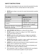
1.   KEEP THE METER DRY

. If it gets wet, wipe it off.

2.   

USE AND STORE THE METER IN NORMAL TEMPERATURES

. Tem-

perature extremes can shorten the life of the electronic parts and distort 

or melt plastic parts.

3.   

HANDLE THE METER GENTLY AND CAREFULLY

. Dropping it can 

damage the electronic parts or the case.

4.   

KEEP THE METER CLEAN. 

Wipe the case occasionally with a damp 

cloth. DO NOT use chemicals, cleaning solvents, or detergents.

5.   

USE ONLY FRESH BATTERIES OF THE RECOMMENDED SIZE AND 

TYPE.

 Remove old or weak batteries so they do not leak and damage 

the unit.

6.  IF THE METER IS TO BE STORED FOR A LONG PERIOD OF TIME,


the batteries should be removed to prevent damage to the unit.

Maintenance

WARNING: 

To avoid electric shock, disconnect the test leads from any source 

of voltage before removing the back cover or the battery or fuse covers.

WARNING: 

To avoid electric shock, disconnect the test leads from any 

source of voltage before removing the battery cover.

WARNING: 

To avoid electric shock, do not operate your meter until the 

battery and fuse covers are in place and fastened securely.

This multimeter is designed to provide years of dependable service, if the 

following care instructions are performed:

1.  Turn power off and disconnect the test leads from the meter.
2.   Open the rear battery cover by removing two screws (B) using a Phillips 

head screwdriver.

3.   Insert the battery into battery holder, observing the correct polarity.
4.   Put the battery cover back in place. Secure with the screws.

Summary of Contents for DMR-6700

Page 1: ...USER S MANUAL Multimeter True RMS DMR 6700 CIRCUIT TEST ELECTRONICS www circuittest com...

Page 2: ...er This WARNING symbol indicates a potentially hazardous situation which if not avoided could result in death or serious injury This CAUTION symbol indicates a potentially hazardous situ ation which i...

Page 3: ...ingequip ment to be supplied from the fixed installation Note Examples include household office and laboratory appliances OVERVOLTAGE CATEGORY III Equipment of OVERVOLTAGE CATEGORY III is equipment in...

Page 4: ...ly When using the test probes always keep fingers behind the finger guards Never touch the exposed probe tip Always consider circuits to be energized Never assume any equipment to be de energized Use...

Page 5: ...OT measure voltage if the voltage on the COM input jack ex ceeds 600V above earth ground 4 NEVER connect the meter leads across a voltage source while the function switch is in the current resistance...

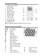
Page 6: ...put jack Note Tilt stand and battery compartment are on rear of unit AUTO Autoranging HOLD Display hold REL Relative Diode test Continuity C Degree Celsius F Degree Fahrenheit DC Direct current AC Alt...

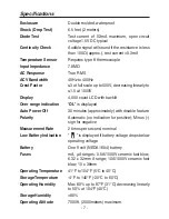
Page 7: ...h backlit Over range indication OL is displayed Auto Power Off 30 minutes approximately with disable feature Polarity Automatic no indication for positive Minus sign for negative Measurement Rate 2 ti...

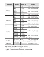
Page 8: ...ing 2 digits 40V 0 01V 400V 0 1V 1000V 1V 1 5 reading 10 digits AC Voltage 400mV 0 1mV 2 0 reading 10 digits 4V 0 001V 2 0 reading 5 digits 40V 0 01V 400V 0 1V 1000V 1V 2 5 reading 5 digits DC Current...

Page 9: ...y 5 999Hz 0 001Hz 1 5 reading 1 digit 59 99Hz 0 01Hz 599 9Hz 0 1Hz 1 2 reading 3 digits 5 999kHz 0 001kHz 59 99kHz 0 01kHz 599 9kHz 0 1kHz 5 999MHz 0 001MHz 1 5 reading 4 digits 9 999mHz 0 001MHz Sens...

Page 10: ...tion 2 Press MODE if required so DC appears on the display 3 Insert the black test lead banana plug into the nega tive COM jack Insert the red test lead banana plug into the positive V jack 4 Touch th...

Page 11: ...AC voltages if a motor on the circuit is being switched ON or OFF Large voltage surges may occur that can damage the meter 1 Set the function switch to the position 2 Press MODE if required so AC app...

Page 12: ...to the yellow 10 HZ position and insert the red test lead banana plug into the 10A jack 5 Press the MODE button to indicate DC on the display 6 Remove power from the circuit under test then open up t...

Page 13: ...na plug into the A mA jack 4 For current measurements up to 10A AC set the function switch to the yellow 10 HZ position and insert the red test lead banana plug into the 10A jack 5 Press the MODE butt...

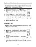
Page 14: ...Press the MODE button to indicate on the display 4 Touch the test probe tips across the circuit or part under test It is best to disconnect one side of the part under test so the rest of the circuit...

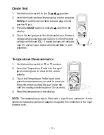
Page 15: ...to measure Keep the probe touching the part under test until the reading stabilizes about 30 seconds 4 Read the temperature in the display Diode Test 1 Set the function switch to the position 2 Inser...

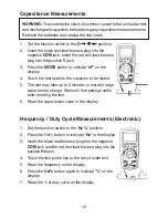
Page 16: ...t leads to the capacitor to be tested 5 The test may take up to 3 minutes or more for large capacitors to charge Wait until the readings settle before ending the test 6 Read the capacitance value in t...

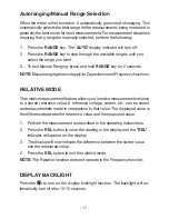
Page 17: ...LATIVE MODE 1 Perform the measurement as described in the operating instructions 2 Press the REL button to store the reading in the display and the REL indicator will appear on the display 3 The displ...

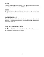
Page 18: ...ty Capacitance or AC and DC Volts and Current AUTO POWER OFF The auto off feature will turn the meter off after approximate 30 minutes of inactivity To disable the auto power off feature hold down the...

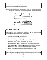
Page 19: ...hould be removed to prevent damage to the unit Maintenance WARNING Toavoidelectricshock disconnectthetestleadsfromanysource of voltage before removing the back cover or the battery or fuse covers WARN...

Page 20: ...the battery 4 Remove the six A screws securing the rear cover 5 Gently remove the old fuse and install the new fuse into the holder 6 Always use a fuse of the proper size and value 0 5A 1000V fast bl...

Page 21: ...period of 2 years from the date of purchase Any product which has been subjected to misuse or accidental damage is excluded from the warranty Except as stated above Circuit Test Electronics makes no p...

Reviews: