48
AFQm
Instruction Manual
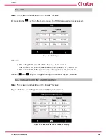
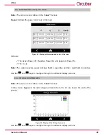
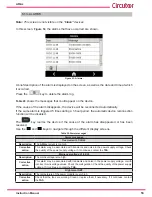
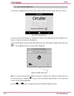
It shows:
The Voltage in each of the phases, L1, L2 and L3.
The Current in the Mains in each of the phases, L1, L2, L3 and Neutral.
The Current in the Load in each of the phases, L1, L2, L3 and Neutral.
The Frequency.
Use the
and
keys to navigate through the different display screens.
6.4.- POWER AND COS ɸ OF MAINS
Note:
This screen is not visible on the
“slave”
devices.
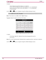
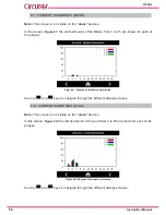
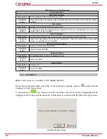
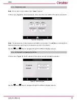
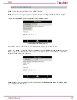
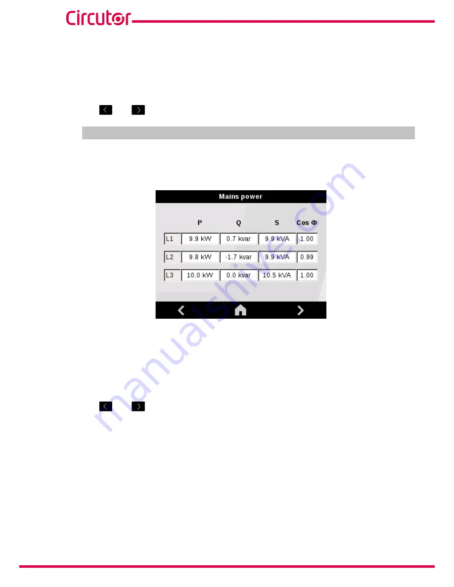
Figure 44
shows the power and cos ɸ of the mains.
Figure 44:
Display of the power and cos ɸ of the mains.
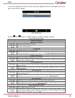
It shows:
The Active Power (P), Reactive Power (Q) and
Apparent Power (S).
The cos ɸ
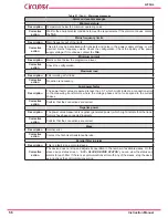
Note:
The - sign in reactive power indicates that it is capacitive and the + sign that it is inductive.
Use the
and
keys to navigate through the different display screens.
Summary of Contents for AFQm Series
Page 1: ...INSTRUCTION MANUAL Active Parallel Multi Function Filter AFQm M217B01 03 19B...
Page 2: ...2 AFQm Instruction Manual...
Page 103: ...103 Instruction Manual AFQm 608 812 1755 665 465 1890 Figure 98 Dimensions Cabinet type AFQm...
Page 105: ...105 Instruction Manual AFQm 14 CE CERTIFICATE...
Page 106: ...106 AFQm Instruction Manual...
Page 107: ...107 Instruction Manual AFQm...

