

67
Instruction Manual
AFQm
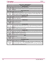
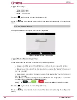
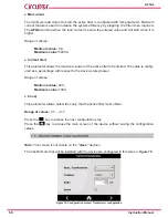
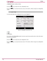
● Num transformers
The number of transformers that will be installed is configured with this parameter, the options
are:
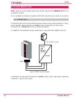
2�
This option can only be used on the 3-wire model,
AFQm-3WF-xxxx
3�
With the option of
2
transformers, you should install a transformer measuring the
L1 phase and another measuring the L2 phase. The L3 phase is left without a
measuring transformer.
In three-phase mains with neutral, 3 transformers are needed to ensure the cor-
rect operation of the device.
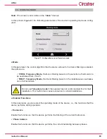
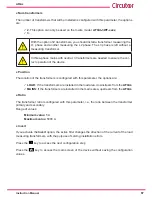
●
Position
The location of the transformers is configured with this parameter, the options are:
LOAD
: If the transformers are installed in the load area, downstream from the
AFQm
.
MAINS
: If the transformers are installed in the mains area, upstream from the
AFQm
.
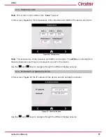
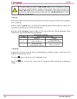
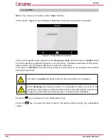
●
Ratio
The transformer ratio is configured with this parameter, i.e., the ratio between the transformer
primary and secondary.
Range of values:
Minimum value:
5 A
Maximum value:
5000 A
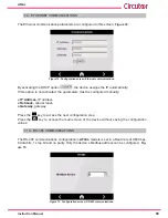
●
Invert
If you activate the
Invert
option, the active filter changes the direction of the current of the load
measuring transformers, with the purpose of solving installation errors.
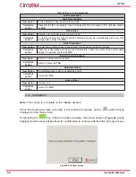
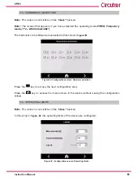
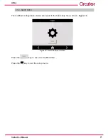
Press the
key to access the next configuration step
Press the
key to access the main screen of the device without saving the configuration
values.
Summary of Contents for AFQm Series
Page 1: ...INSTRUCTION MANUAL Active Parallel Multi Function Filter AFQm M217B01 03 19B...
Page 2: ...2 AFQm Instruction Manual...
Page 103: ...103 Instruction Manual AFQm 608 812 1755 665 465 1890 Figure 98 Dimensions Cabinet type AFQm...
Page 105: ...105 Instruction Manual AFQm 14 CE CERTIFICATE...
Page 106: ...106 AFQm Instruction Manual...
Page 107: ...107 Instruction Manual AFQm...