background image

 4.- STATIC CAPACITOR BANK START-UP


 4.1.- BEFORE START-UP

The static capacitor banks include a power factor regulator. 

Prior to start-up, the operation of said regulator must be known; for this reason, all capacitor 

banks come with the specific manual of the regulator being used. 

Ensure you have this manual available for the start-up process. 

For the 

OPTIME EMS-C

, the regulator must have a 

Computer Max 6f V12dc

 type, 12 Vdc 

static output control voltage, or equivalent.

Carrying out the adjustment of the regulator incorporated in the capacitor bank, 

and carrying out an optimum start-up, requires that the installation load be at least 

30% or 40% of the nominal load for which the capacitor bank has been sized. 

If all the stages are not arriving, the connection can be done manually to check 

them all.

The  entire  capacitor  bank  should  not  be  connected  manually  during  low  load 

moments, because under certain circumstances it could produce resonance phe-

nomena with the installation's power transformer.


 4.2.- START-UP

Apply the safety regulations listed in section “

3.- INSTALLATION

 of this manual 

before operating the units.

The National Electric Code of the country where the capacitor bank is in-

stalled or operated should be strictly followed.

1.-

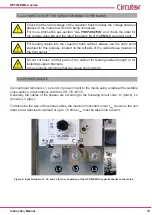
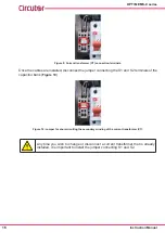
 Ensure the internal two-pole circuit breaker that starts the regulator (shown in 

Figure 11

) is 

in place.

Figure 11: Two-pole circuit breaker of the regulator power circuit .

17

Instruction Manual

OPTIM EMS-C series  

Summary of Contents for Optim EMS-C Series

Page 1: ...INSTRUCTION MANUAL M057B01 03 19A Low voltage capacitor bank with static switching operation OPTIM EMS C series...

Page 2: ...2 OPTIM EMS C series Instruction Manual...

Page 3: ...owing should be taken into consideration Incorrect handling or installation of the unit may result in injury to personnel as well as damage to the unit In particular handling with voltages applied may...

Page 4: ...4 3 9 CURRENT TRANSFORMER CT CONNECTION 15 4 STATIC CAPACITOR BANK START UP 17 4 1 BEFORE START UP 17 4 2 START UP 17 4 3 CHECKS AFTER THE CAPACITOR BANK IS CONNECTED AND THE REGULATOR ADJUSTED 19 5 M...

Page 5: ...ion 10 14 M057B01 03 14A Initial Version 11 19 M057B01 03 19A Changes in the following sections 3 2 4 2 10 Note The images of the units are solely for the purpose of illustration and may differ from t...

Page 6: ...er precautions and using the proper manual and mechanical tools so as not to damage it If the unit is not to be immediately installed it must be stored at a location with a firm and level floor and th...

Page 7: ...nit The necessary precautions must be taken to prevent the unit from tipping over during abrupt operations Figure 2 Unloading with a forklift 1 3 STORAGE The following storage recommendations shall be...

Page 8: ...etwork cycle These outputs provide a 12 Vdc activation signal to the and inputs of the connection control ler boards as opposed to the CPC4 type zero voltage Fast regulators enable regulation with min...

Page 9: ...gram of the CPC4 to the power block 2 1 3 POWER BLOCK The power block of an OPTIM EMS C unit consists of 2 to 4 groups of thyristor diode semicon ductors three phase capacitor three pole circuit break...

Page 10: ...mstances that compromise safety immediately stop work in that area and disconnect the unit in order to check it without voltage The manufacturer of the unit is not responsible for any damage resulting...

Page 11: ...could damage it and electrocute the person handling it 3 2 PREPARATION CIRCUTOR OPTIM EMS C static capacitor banks come ready for easy installation and start up Remove the packaging of the unit and v...

Page 12: ...nded leaving at least a 20 cm separation between adjacent cabinets Note Static units have an aluminium heatsink to cool the thyristors Periodically clean these heatsinks with a brush or with compresse...

Page 13: ...r parts of the cabinet for feeding cables through or for installing support brackets It may produce trimmings that can cause short circuits 3 5 POWER CIRCUIT Connect input terminals L1 L2 and L3 power...

Page 14: ...egulator that measures the current in a single phase we advise installing the current transformer CT in the phase connected to L1 black cable The CT S1 and S2 outputs must be connected to the terminal...

Page 15: ...ank If the CT must be installed while the installation is under load short circuit S1 and S2 while they are not connected to the capacitor bank The current value of the CT primary winding must be equa...

Page 16: ...S2 terminals of the capacitor bank Figure 10 Figure 10 Jumper for short circuiting the secondary winding of the current transformer CT Any time you wish to change or disconnect a current transformer...

Page 17: ...least 30 or 40 of the nominal load for which the capacitor bank has been sized If all the stages are not arriving the connection can be done manually to check them all The entire capacitor bank shoul...

Page 18: ...shown in Figure 13 we recommend connecting the current transform er on phase L1 and drawing the voltage power supply from phases L2 and L3 Figure 12 Computer Max Regulator Photo for illustrative purpo...

Page 19: ...n 1 3 times this value continuously Continuous consumption in all the capacitors over the nominal value may be caused by the presence of harmonics in the mains or an excessively high power supply volt...

Page 20: ...terminals clean Check that the thyristors are not short circuited To do so check that if you cut the power supply of the regulator there is no current in any of the capacitor phases Check that the ca...

Page 21: ...wdust metal trimmings etc Vacuum the dust and solid waste regularly There is no estimated time frame for cleaning it depends on the amount of dirt that penetrates the cabinet of the capacitor bank 5 2...

Page 22: ...that some of the thyristors are defective and are short circuited Check the consumption of the different steps in each phase The normal values are shown in Table 5 in accordance with the power of each...

Page 23: ...e is always provided with the capacitor bank Make sure that there are no damaged segments on the display abnormal brightness Make sure that the regulator s keyboard is working properly Enter Setup and...

Page 24: ...Protections Internal fuses and over pressure system In accordance with Standards UNE EN 60831 Environmental features Maximum temperature of capacitors Category D in accordance with EN 60831 1 Maximum...

Page 25: ...1 Radiador 700mm V1 V2 1 3 2 4 5 Paso 2 U1 U2 1 3 2 V1 V2 1 3 2 4 5 Paso 3 U1 U2 1 3 2 V1 V2 1 3 2 4 5 Paso 4 U1 U2 1 3 2 V1 V2 1 3 2 4 5 4 5 PLACA 1G1 CPC CONTROL 1K1 PLACA 1G1 CPC CONTROL 1K1 PLACA...

Page 26: ...oper installation or improper usage of the unit Consequently this guarantee does not apply to failures occurring in the following cases Overvoltages and or electrical disturbances in the supply Water...

Page 27: ...10 CE CERTIFICATE 27 Instruction Manual OPTIM EMS C series...

Page 28: ...28 OPTIM EMS C series Instruction Manual...

Page 29: ...29 Instruction Manual OPTIM EMS C series...

Page 30: ...CIRCUTOR SA Vial Sant Jordi s n 08232 Viladecavalls Barcelona Tel 34 93 745 29 00 Fax 34 93 745 29 14 www circutor es central circutor es...

Reviews: