background image

 2.- PRODUCT DESCRIPTION

The purpose of this manual is to assist during the installation, start-up and maintenance of 

OPTIM FRS/FR P&P

 series low voltage (LV) capacitor banks with detuned filters, switched by 

contactors. Carefully read the manual to get the best performance from these devices.

 3.- INSTALLATION


3.1.- PRELIMINARY RECOMMENDATIONS

In order to use the device safely, it is critical that individuals who handle it follow 

the safety measures set out in the standards of the country where it is being used, 

use the personal protective equipment necessary, and pay attention to the vari-

ous warnings indicated in this instruction manual.

Installation or maintenance personnel should read and understand this manual 

before operating the device.

A copy of this manual should always be available to maintenance personnel for 

reference purposes

Connecting the device to the public mains must be carried out in compliance with 

the EN-IEC60204-1 standard, regarding the safety of LV electrical installations.

It is recommended that several personnel are present when handling the device 

for installation or maintenance. 

If damage or faults are detected during device operation, or in circumstances that 

compromise safety, immediately stop work in that area and disconnect the device 

in order to check it without voltage.

The manufacturer of the device is not responsible for any damage resulting from failure by the 

user or installer to heed the warnings and/or recommendations set out in this manual, nor for 

damage resulting from the use of products or accessories that did not come with the device or 

that were made by other manufacturers.

If an anomaly or malfunction is detected in the device, do not use it to perform any operation.

Modifying, upgrading or rebuilding the device without written authorisation from 

the manufacturer is prohibited.

The  installation,  operation  and  maintenance  of  low  voltage  (LV)  devices  must 

only be carried out by authorised installers. LV regulations (Art. 22) specifically 

define the requirements that authorised installers must meet.
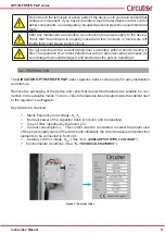
Do not access the active elements of a capacitor bank with static operation that 

has been powered and might have voltages present. Wait at least 

5 minutes

 af-

ter the power supply has been disconnected. 

8

OPTIM FRS/FR P&P series 

Instruction Manual

Summary of Contents for OPTIM FR P&P Series

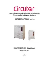
Page 1: ...INSTRUCTION MANUAL M090B01 03 19A Low voltage capacitor banks with detuned filters switched by contactors OPTIM FRS FR P P series...

Page 2: ...2 OPTIM FRS FR P P series Instruction Manual...

Page 3: ...ing should be taken into consideration Incorrect handling or installation of the unit may result in injury to personnel as well as damage to the unit In particular handling with voltages applied may r...

Page 4: ...K START UP 15 4 1 BEFORE START UP 15 4 2 START UP 15 4 3 CHECKS ONCE THE CAPACITOR BANK HAS BEEN CONNECTED AND THE REGULATOR HAS BEEN ADJUSTED 16 5 MAINTENANCE 18 5 1 SAFETY REGULATIONS 18 5 2 MAINTEN...

Page 5: ...A Changes in the following sections 3 9 04 16 M090B01 03 16B Changes in the following sections 3 9 11 19 M090B01 03 19A Changes in the following sections 3 2 4 2 10 Note The images of the devices are...

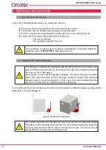
Page 6: ...recautions and using the proper manual and mechanical tools so as not to damage it If the device is not to be immediately installed it must be stored at a location with a firm and level floor and the...

Page 7: ...The neces sary precautions must be taken to prevent the device from tipping over during abrupt operations Figure 2 Unloading with a forklift 1 3 STORAGE The following storage recommendations must be...

Page 8: ...nt when handling the device for installation or maintenance If damage or faults are detected during device operation or in circumstances that compromise safety immediately stop work in that area and d...

Page 9: ...PREPARATION The CIRCUTOR OPTIM FRS FR P P static capacitor banks come ready for easy installation and start up Remove the packaging of the device and verify that its electrical features are suitable...

Page 10: ...least 20 cm of separation be maintained between the sides of adjacent cabinets Make sure the device can be accessed easily The environmental conditions of the place where the device is installed must...

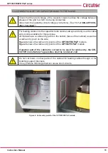
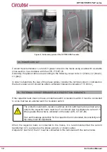
Page 11: ...ry point on the bottom base of the cabinet as well as a cable entry point on the side Figure 4 shows the cable entry points of the OPTIM FRS P P models Figure 5 shows the cable entry points of the OPT...

Page 12: ...acitor bank does not have an internal switch or isolation switch it must be connected to a line that has an external switch or isolation switch The protection elements isolation switches and or switch...

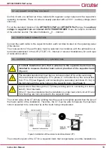
Page 13: ...must be installed to measure the total load current plus that of the capacitor bank Figure 6 The standard transformer must have a nominal output of 5 A at the secondary We recommend connecting the CT...

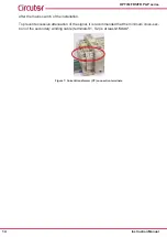
Page 14: ...excessive attenuation of the signal it is recommended that the minimum cross sec tion of the secondary winding cable terminals S1 S2 is at least 2 5 mm2 Figure 7 Current transformer CT connection ter...

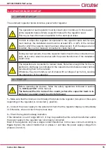
Page 15: ...s label before reconnecting them to the network Otherwise they could start up out of phase with a voltage of up to 2xUn causing the destruction of the capacitor 4 2 START UP Before operating the devic...

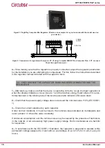
Page 16: ...A sign of proper operation is when the display indicates a cos close to 1 and the reactive energy meter stops if it is elec tromechanical or the blinking rate of the kvar h pulse ratio indicator LED...

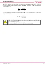
Page 17: ...p 100 V V RED C 5 To check the filter s correct tuning make sure that the voltage on the terminals of each wind ing of the reactor is 100 100 p p V V RED L Check the working temperature of the capaci...

Page 18: ...y the condition of the contacts on the operation elements Check that the capacitor current is not lower than 25 nor greater than 120 of the nominal value by phase and that there is no phase unbalance...

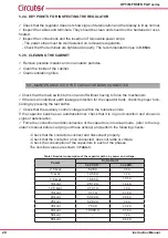
Page 19: ...dust sawdust rust particles etc vacuum the contactor periodically There is no estimated time frame for cleaning it depends on the amount of dirt that is inside the capacitor bank 5 2 3 KEY POINTS FOR...

Page 20: ...by pressing the test button Check that the auxiliary control voltage is within the tolerance limits If the capacitor bank has an autotransformer check that it is in good condition and shows no signs o...

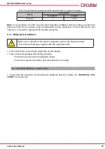
Page 21: ...with another capacitor 5 3 1 REGULATOR CHECKS Refer to the manual of the specific regulator used in the capacitor bank This manual is always supplied with the capacitor bank Check that there are no f...

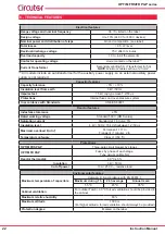
Page 22: ...accordance with Standards UNE EN 60831 Reactor features Inductance tolerance 5 Rated working voltage Standard 500 V RMS value Saturation current Standard at 1 8 In L 5 Insulation level 4 kV 50 Hz 15...

Page 23: ...citor banks UNE EN 61921 2004 Low voltage switchgear sets Part 1 General rules UNE EN 61439 1 2012 7 STANDARD ELECTRICAL DIAGRAMS The electrical diagrams indicated in this manual are for the standard...

Page 24: ...Q5 AT1 3x16 63A Icu 6kA 400VCA 3x16 63A Icu 6kA 400VCA 3x16 63A Icu 6kA 400VCA 3x16 63A Icu 6kA 400VCA 3x200 250A OPTIM FRS P P 08232 Viladecavalls Barcelona Vial Sant Jordi s n S1 S2 S1 S2 1 2 3 4 S...

Page 25: ...V 3N A3 BAT AUT COND FILTROS R RG1 TB1 TB1 Q1 AT1 08232 Viladecavalls Barcelona Vial Sant Jordi s n 1S1 1S2 S1 S2 1 2 3 4 5 6 Paso 1 Paso 2 Paso 4 S2 S1 C6 C5 C4 C3 C2 C1 Com cos I 0V 230V 400V 2x6A P...

Page 26: ...V 3N A3 BAT AUT COND FILTROS R RG1 TB1 TB1 Q1 AT1 06232 Viladecavalls Barcelona Vial Sant Jordi s n 1S1 1S2 S1 S2 1 2 3 4 5 6 Paso 1 Paso 2 Paso 6 S2 S1 C6 C5 C4 C3 C2 C1 Com cos I 0V 230V 400V 2x6A P...

Page 27: ...A3 BAT AUT COND FILTROS R RG1 TB1 TB1 Q1 AT1 08232 Viladecavalls Barcelona Vial Sant Jordi s n 1S1 1S2 S1 S2 1 2 3 4 5 6 Paso 1 Paso 2 Paso 8 S2 S1 C6 C5 C4 C3 C2 C1 Com cos I 0V 230V 400V 2x6A Paso 3...

Page 28: ...ilures occurring in the following cases Overvoltages and or electrical disturbances in the supply Water if the product does not have the appropriate IP classification Poor ventilation and or excessive...

Page 29: ...10 CE CERTIFICATE 29 Instruction Manual OPTIM FRS FR P P series...
Page 30: ...30 OPTIM FRS FR P P series Instruction Manual...

Page 31: ...31 Instruction Manual OPTIM FRS FR P P series...
Page 32: ...CIRCUTOR SA Vial Sant Jordi s n 08232 Viladecavalls Barcelona Tel 34 93 745 29 00 Fax 34 93 745 29 14 www circutor es central circutor es...

Reviews: