23
Instruction Manual
RECmax-CVM
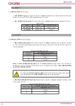
Digital output
(terminals 7 and 8 in
) can work as an alarm for the measurement
variables, to indicate that they are outside the programmed limits or to generate energy pulses,
7.3.11.5. PROGRAMMING THE DIGITAL OUTPUT
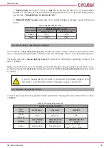
BREAKER ON/OFF output
(terminals 16, 17 and 18 in
) indicates status of the main
switch�
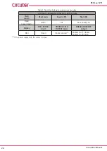
Table 12: BREAKER ON/OFF output�
Main switch
BREAKER ON/OFF output
Contact 16 - 17
Contact 16 - 18
Closed
Open
Closed
Open
Closed
Open
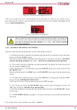
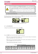
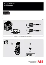
4�8�- RESET LEVER AND MANUAL LOCKING
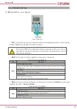
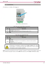
The device has a
reset lever (see
), its default position is down� In case of reclosing, the motor
lever is raised actuating the switch� After the reset, the motor lever returns to its downward position�
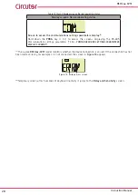
The device also has a
manual locking system
to prevent the possibility of automatic reclosing� The
lever is sealable�
Reclosing of the device can be completely prevented through manual locking� The operation is per-
formed by moving the
reset lever
downwards and moving
the manual locking system
(yellow catch)
to the left�
In case of manual locking, the device is connected to the power supply� There-
fore, there is a risk of electric shock if the power supply is not cut off�
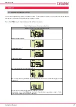
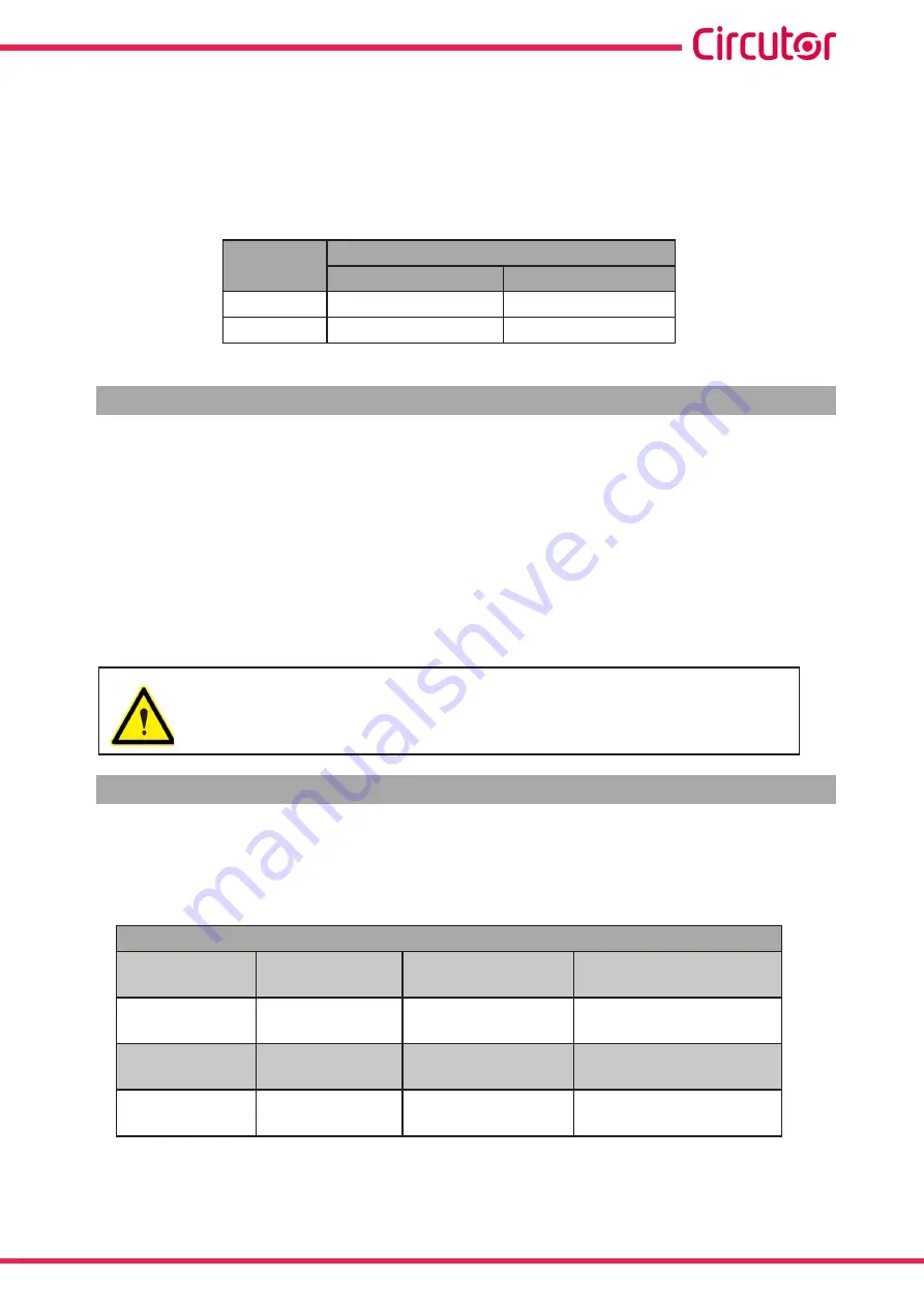
4�9�- NORMAL OPERATING STATUS
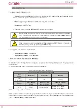
In normal operating conditions, powered device and without tripping, the status of the device is shown
Table 13: Normal operating conditions�
Normal operating conditions
Main
switch
Reset lever
Green LED
Red LED
Closed
(Lever up)
Down
Power on
Off
Display
REC LOCKED
Alarm
POSITIVE SAFE
OUTPUT Alarm
BREAKER ON/OFF
output
Green
open contact
closed contact
contact 16-17: open
contact 16-18: closed


