23
Instruction Manual
SVGm
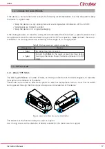
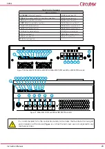
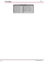
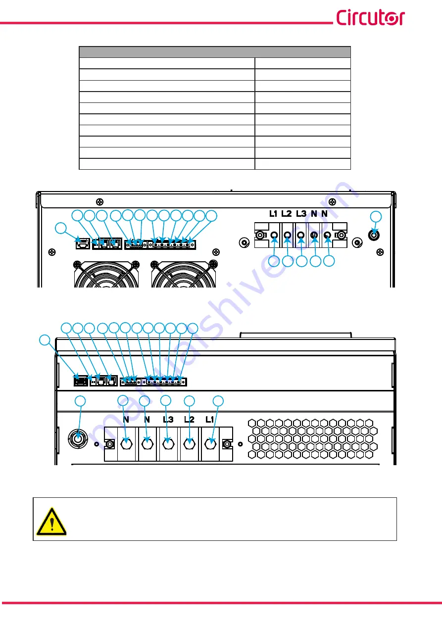
Table 14: List of terminals�
Device terminals
1:
ETHERNET
, Ethernet Connector
11: S2
, Current input L2
2:
R
BUS
, Terminator switch for parallel connection
12: S1,
Current input L3
3:
IN
, Input for parallel connection
13: S2
, Current input L3
4: OUT
, Output for parallel connection
14: L1
, Mains connection L1
5: A,
RS-485 communications
15: L2
, Mains connection L2
6: B,
RS-485 communications
16: L3
, Mains connection L3
7: S,
RS-485 communications
17: N
, Mains connection N
8: S1,
Current input L1
18: N
, Mains connection N
9: S2
, Current input L1
19:
Earth connection
10: S1,
Current input L2
ETHERNET
LINK
IN
OUT
RS485
S1
S1
S1
S2
S2
S2
L1 L2 L3
1
3
4
5
6
7
8
9 10 11 12 13
14 15 16 17 18
19
RBUS
2
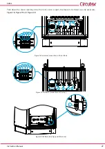
Figure 10: SVGm-3WF-030M, SVGm-4WF-020M, SVGm-3WF-060M and SVGm-4WF-040M terminals�
ETHERNET
LINK
IN
OUT
RS485
S1
S1
S1
S2
S2
S2
L1 L2 L3
1
3
4
5
6
7
8
9 10 11 12 13
RBUS
2
A B S
14
15
16
17
18
19
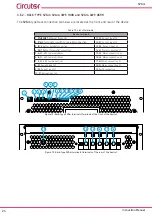
Figure 11: SVGm-3WF-100M and SVGm-4WF-069M� terminals�
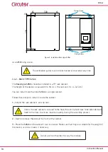
It is recommended to fix the connection cables to the holes that facilitate the transport
and installation of the device (
), so that the terminals are not subjected to any
mechanical stress.


