background image

Cirris 4200 Series User Manual  

Version 2019.2.1

© 2018 Cirris Systems Corporation

401 North 5600 West

Salt Lake City, Utah 84116

U.S.A.

www.cirris.com

Summary of Contents for 4200 Series

Page 1: ...Cirris 4200 Series User Manual for 4200 4250 Testers ...

Page 2: ... Create a New Test Program 15 7 1 1 Edit Learn Settings 15 8 Test Preferences 16 9 Low Voltage 18 10 High Voltage Hipot 4250 only 20 10 1 High Voltage Testing 20 10 2 Basic Settings 20 10 3 Advanced Settings 21 10 3 1 Dielectric Withstand Test 21 10 3 2 Insulation Resistance Test 21 10 4 Options 22 11 Reports 23 11 1 Editing Report Templates 24 12 Digital I O 26 12 1 Inputs 26 12 2 Outputs 27 13 C...

Page 3: ... Defaults 42 22 Network Settings 43 22 1 Ethernet 43 22 2 Wi Fi 44 22 2 1 Connecting to Cirris Hub 44 23 High Voltage Guidelines 4250 only 45 24 Four Wire Kelvin Testing 47 25 Calibration 49 26 Connecting to Easy Wire 50 27 Frequently Asked Questions 51 27 1 Service and Maintenance 51 27 2 Connector Maintenance 51 27 3 Repair 52 28 Factory Defaults 53 29 Troubleshooting 55 30 Glossary 56 31 Specif...

Page 4: ...ailed the test 1 2 Intended Use Your 4200 Series tester is intended to be used indoors at a temperature of 50 104 degrees Fahrenheit 10 40 degrees Cel sius Best performance can be obtained at a relative humidity of less than 70 Insulation Resistance measurements will degrade at over 70 relative humidity Never apply live voltages to the test points or probe input of your Cirris tester Power supplie...

Page 5: ...g the tester Handles are provided on the front of the tester to make lifting and carrying the tester more convenient 1 3 5 User Precautions To help ensure safety during testing Cirris offers different tools such as switches mats and light curtains that can help create a safe testing environment These tools are not necessary but are recommended to ensure safety during testing See cirris com safety ...

Page 6: ... where there should be no current A hipot test takes two conductors that should be isolated and applies a very high voltage between the conductors If too much current flows the points are not well isolated and they fail the test Hipot tests are helpful in finding Nicked or crushed insulation Stray wire strands or braided shielding Conductive or corrosive contaminants around the conductors Terminal...

Page 7: ...his error occurs because the tester expects to measure a certain amount of current but a larger amount of the current flows through the wire than the tester expects The tester assumes the current is escaping and reports an overcurrent error Often this error is attributed to capacitance With wires acting as conductors and insulation acting as a barrier cables can build up high amounts of capacitanc...

Page 8: ...le Probe Antenna USB flash drive containing software documentation Optional Adapters expansion boxes tilt stands and other accessories 3 2 Front of Tester a 7 full color graphical display with capacitive touch screen 800 x 480 pixel resolution b Cirris adapter system creates an easy fixturing setup system c High voltage warning symbol d Handles for portability a b c d ...

Page 9: ...programs and other information f Ethernet Use an ethernet cable to connect your tester for network printing and back up g Antenna Beta Connect wirelessly to network printers and back up h Power Cord Attach the power cord i Power button Turns tester on and off 3 4 Setting up the Tester Set Up Test Hardware 1 Connect the power cord to your tester 2 Plug the power cord into a grounded outlet surge pr...

Page 10: ... your country s AC line frequency The correct selection will improve test measurement accuracy 1 From the Main Menu press System Settings 2 Press the Mains Frequency button to switch it to either 50 or 60 Hz 3 Press Done to return to the Main Menu Note For more setup options such as changing the language or volume see System Settings onpage 41 3 5 Install Expansion Boxes Each expansion box adds an...

Page 11: ...adapter position You may also consider using removable stickers for this purpose For example you could continue the number system and label each adapter position as J5 J6 J7 etc If you are attaching more than one expansion box repeat the procedure If your system uses all seven expansion boxes you will need to purchase a second cable Contact your account manager at Cirris for more information and t...

Page 12: ...is an essential part of ensuring the accuracy of test results and maximizes the test station s throughput This means fixturing needs to be at least as good if not better than the quality of your DUT Remember you want to test the DUT not the fixturing Cirris makes generic mating cables with one end that connects to the tester while the other end has unterminated wires These cables save time by comp...

Page 13: ...in the software which allows networed testers to access these changes Network Printing Print all test reports from any printer connected to the network with Cirris Hub Software Server Configuration Select where you want your files stored and organized on your system Tester Organization Give names to testers and define their printers A free version of the software is found on the USB flash drive th...

Page 14: ...e settings for a loaded test program View View details of a loaded test program Test Perform a test using the loaded test program Create New Create a new test program Load Load an existing test program to edit view or test Manage Files Copy move or delete test programs and files System Settings Perform a variety of tasks related to the setup and maintenance of the tester software including changin...

Page 15: ...only page 20 Reports page 23 Digital I O page 26 Components New test only page 28 Data Collection page 29 Components can only be edited when creating a new test program and cannot be altered after a test program has been Learned except by using a text editor on a computer Note The next time you open Edit Learn Settings for a new test program the last input settings will be applied to the test prog...

Page 16: ...e high voltage test starts Auto Start The high voltage test will automatically start after a slight delay The delay is used to allow operators sufficient time to ensure their hands are free of the tester before the high voltage test begins Intermittents Test An intermittents test repeatedly performs a low voltage test to give the operator time to catch problems that might only occur intermittently...

Page 17: ... ability to press START TEST on the tester display External Safety Swtich Safety Switch requires that the tester sees a high signal on pin 2 of the digital I O connector before starting the hipot test Safety Switch can be used to help ensure an operator does not shock themselves during a hipot test Safety Switches can be dual palm switches wired in series a foot pedal or a sensor in automated test...

Page 18: ...A measurement above the LV Insulation Resistance Value will be reported as an open error Connection Resistance 0 0 Ω Ω High Resistance Good Opens LV Insulation Resistance LV Insulation Resistance Intended connections above the LV insulation resistance value are considered open during a low voltage test and ignored during a Learn Range 0 1 ohm 5 0 M ohm As shown in the graphic below during a shorts...

Page 19: ...rrors for intended connections if there are com ponents in the test This value has no impact on whether an intended connection passes or fails but does influence whether a failing connection is labeled as High Resistance or Open Connection Resistance Component Resistance 0 0 Ω Ω Opens Good LV Insulation Resistance High Resistance As shown in the graphic below the Component Resistance value has no ...

Page 20: ...green while the other button will turn blue Options Adjust other settings having to do with the high voltage test such as selecting which pins will be included in the test whether a high cap shield is present on the cable and if you want to use high speed mode 10 2 Basic Settings High Voltage Set the voltage limits required for your cable s specifications Insulation Resistance Set the resistance l...

Page 21: ...Range 5 0 M 1000 M ohm IR Dwell Time The amount of time the IR Resistance value must remain good to pass the test this is how long the test will run after soak time The reported resistance value for the IR test is an average of the measurements taken over this time Range 2 mS 120 S Note Because the reported value is an average this setting can also be used to filter out noise caused by the AC powe...

Page 22: ...fails when any error occurs regardless of the cause Note High Cap Shield is available to assist with highly capacitive shields which would fail with standard high voltage settings By turning on the High Capacitance Shield setting you can successfully test a cable with a high capacitive shield High Speed Mode The HV test applies a voltage to multiple nets simultaneously while still ensuring that ea...

Page 23: ...om the list and press Add 3 Edit the report to meet your requirements You can change the following criteria Report Name Change the name of the report to your prefer ence Template Use a built in template or a custom template de signed in Cirris Hub Software Printer Select which printer you would like to print the report You may have several network printers to choose from or you may select a label ...

Page 24: ... like to edit these reports connect your tester to a PC Navigate to the hidden reports file see below and make any necessary edits to the templates in a text editor Save the template as a prn file and replace the current template with the revised version Note Currently the font size and style such as bold cannot be changed on reports Capitalization can be used when needed for emphasis This limitat...

Page 25: ...rn on the tester the default template will be restored Tokens Specific information included on the label from the tester such as test results time and date is written on the label in the form of tokens Tokens must be written in a Zebra font on the label exactly as shown below Available tokens include TestName Date Time ErrorDetails TestStatus TesterID TesterType LotID Adapters DeviceDescription De...

Page 26: ...for bad test 13 N A 4 Input 9 Power 5 VDC 100 mA max 14 Ground 5 Output 10 Output 15 Ground To use the External Switch input you must set the test program s Start Condition to Press Button 12 1 Inputs The 4250 tester has two inputs pins 1 and 2 The low voltage input is on pin 1 of the digital I O connector If a DC 5 volt logic high is ap plied to pin 1 the tester behaves as if START TEST were pres...

Page 27: ...o limit the current going through it How do you choose the resistor The LED in this instance has a forward bias voltage drop of two volts there fore three volts must drop across the current limiting resistor Knowing the voltage drop is three volts across the resistor and the desired current is 20 mA Ohms Law can be used to determine the resistor value V I R 3V 20mA 150 Ohms In this example you wou...

Page 28: ... the required component to add it to the test program On The component type will be Learned by the tester and added to the test program Off The test program will not include the component Although tolerences that are automatically set during the Learn review the test program to verify that the measured value of the components is the nominal vaue One way to review the values is through a text edito...

Page 29: ...ripting Custom per Cable if stored in Scripting Measured Values Net or Instruction Label Net or Instruction Measurement Error Text Error Number Error Code Error Type Error Text The data is stored in the file tester serial number c_d and can be accessed through a text editor or SPC Link included in the SPC Data Collection software from Cirris Use a USB cable flash drive or network cable to open the...

Page 30: ... in a default location The next time a Learn is performed selecting Save will overwrite the test program saved in the default location If you save the test location in the default location the test program will be overwritten the next time you press Save when creating a new test program Save As By pressing Save As you will be able to select a storage location and name for the test program a Naviga...

Page 31: ... using a text editor 1 Using the provided USB cable connect the tester to a PC Make sure the tester is turned off 2 Connected to a computer the tester will behave like a flash drive In File Explorer navigate to the tester labelled 4200 SERIES 3 Test Programs are visible inside the tester file Open the test program in a text editor such as Notepad 4 You can edit the test name change point labels mo...

Page 32: ...type the original point name and the new point name as shown in the example LABELS J1 001 Point_01 J1 002 Point_02 J1 003 Point_03 J1 004 Point_04 J1 005 Point_05 J1 006 Point_06 J1 007 Point_07 J1 008 Point_08 J1 009 Point_09 J1 010 Point_10 J1 011 Point_11 4 Save the file and close the program 5 Turn on the tester Load the edited test program From the Main Menu press View to see the changes to t...

Page 33: ...turned off the space next to Lot ID will be left empty Good Bad Total Tracks number of cables tested including how many cables passed and failed Print Press button to print test results if a report was selected for the test Test Results This box will display one of three statuses Not Tested Passed Failed Result Details Passes fails and error details from each test Low Voltage High Voltage Intermit...

Page 34: ...ly during the high voltage test 7 The tester will perform a high voltage test checking for current leakage and dielectric failures 8 When the High voltage hipot test finishes the Intermittents Test will begin if an Intermittents Test was included in the test program 16 1 3 Intermittents Test 9 The Intermittents Test allows the user to check for potential defects Flex and move the cable while the t...

Page 35: ... on the right side of the screen If an error occurred the details of the error will be dis played See page 36 to learn about interpreting test results 16 3 Printing Reports In order for reports to print the report must be added to the test program during setup When you press the Print button a list of available reports will appear in a window Select the report you wish to print and press OK If Aut...

Page 36: ... an Open error between test points J1 001 and J1 014 and a short from J1 014 to J1 002 Component Errors When the tester creates a new test program containing a component it will measure the component value in the sample device and assign a default tolerance range During a test if the tester measures a value outside of the tolerance range the component instruction will fail with an error message th...

Page 37: ... be the result of a highly capacitive net such as a shield The 4250 tester has a setting that can overcome an error caused by highly capacitive shields See page 20 Leakage Error This error is an indication that the measured insulation resistance is lower than specified by the IR Resistance test setting HV Errors Graph The graph represents a normal good set of high voltage tests The red line repres...

Page 38: ...Printing The 4200 Series can print from any network printer This is possible through Cirris Hub Software on a network PC Once you install Cirris Hub Software you will be able to print to any printer connected to the network See the Cirris Hub Software Installation Guide for more information 18 2 Label Printing 4200 Series testers print labels using any Zebra Programming Language ZPL capable printe...

Page 39: ...lect a program or file and press Delete Confirm that you want to delete the program or file by pressing Continue WARNING There is no recovery option after a test program or folder is deleted Verify the file selected before you delete any files 19 1 Test Program Backup via PC Connection By connecting your tester to a PC you can move files to and from the PC like you would with a USB flash drive Thi...

Page 40: ...Local Test Program Backup via USB Drive To back up test programs 1 Insert a USB drive into the USB port on your tester 2 Copy your test programs onto the USB drive 3 Remove the USB With the test programs on the USB drive you can save them onto a PC for safe keeping or for editing through a text editor Other USB drive uses Update Firmware Copy test programs between 4200 Series testers Copy test pro...

Page 41: ...lf test to verify that the system is functioning correctly If you suspect anything wrong with the tester you can run a self test If the tester fails a self test a window will open with a description of the details of the failure Note the details of the failure and contact Cirris Tech Support Network Settings Adjust settings to connect to a network For more information see the Cirris Hub Software M...

Page 42: ...n a test by test basis If you change one test program it has no effect on other test programs To use test programs from a legacy tester set the Legacy Defaults on your 4200 Series tester to match the system settings of your legacy Cirris tester Once a legacy test program has been edited and saved on a 4200 Series tester the new test level settings will be applied The same test program can still be...

Page 43: ...de Ethernet Server IP address for the computer running Cirris Hub Soft ware The tester will automatically detect the IP address of the computer running Cirris Hub Software If the tester is on the same subnet Enter the IP address or host name of the computer running Cirris Hub Software if the network service is not de tected Note Generally you will want to have a static IP address assigned to the c...

Page 44: ...de tected Port You do not have to enter a port if the tester automatically detects the Cirris Hub Server on its subnet The de fault port is 12568 or enter the port number as set up by the IT administrator If a client CA Certificate is required insert a USB drive containing the certificate into the USB port on the back of the tester Press Add CA Cert to access the certificate 2 Press Done The teste...

Page 45: ... voltage that can be applied to the cable HV Insulation Resistance Table The HV Insulation Resistance settings are limited by the high voltage settings The table below shows the available Insulation Resistance settings at each of the high voltage settings Voltage Min IR Meg Max IR 100 V 10 100 200 V 20 200 300 V 30 300 400 V 40 400 500 V 50 500 600 V 60 600 700 V 70 700 800 V 80 800 900 V 90 900 1...

Page 46: ...ry out your insulation A shorter soak time or not having soak time is more likely to fail due to humidity related problems Dielectric Withstand Duration A longer duration provides a more stringent test for predicting dielectric failures exhibited as sudden arcs howev er equivalent dielectric errors can be found by compensating a shorter duration with a higher high voltage setting A longer duration...

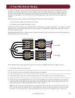
Page 47: ...owing illustration shows a common way wires attached to the T1 and T2 test points could connect to the pins and cavities in the mates to DUT connector On a 4200 Series tester you can tell which type each test point is by probing the point while setting up a Learn 1 From the Main Menu press Create New 2 From the Learn menu press Edit Learn Settings then press Components 3 In the Components menu pre...

Page 48: ...or example on a different connector The location where the four wire pair physically joins the test point connection of the device under test should be placed as close to the device under test as possible The tester will measure any resistance from the fixturing exposed after the four wire pair joins together For more information on four wire testing visit cirris com ...

Page 49: ... to determine if your tester meets calibration standards If the tester passes the performance check your tester is certified to run for another two years If your tester fails the performance check speak to your Cirris sales rep Cirris or a third party lab can calibrate your tester No external adjustments can be made to fix the tester s calibration Do not open the tester chassis or make any attempt...

Page 50: ...d USB cable to connect your tester to a PC that is running Easy Wire Contact your sales representative for information on obtaining a software license Easy Wire Software provides extra features and benefits such as More reporting options Compatibility with other Cirris testers More detailed test creation And other features See cirris com for more information ...

Page 51: ... leaves our factory is calibrated in compliance with ANSI NCSL Z540 1 1994 and ISO 10012 to stan dards traceable to the NIST in the United States For more information visit cirris com The calibration of the tester should be verified annually Where do I find current manuals The most current manuals can be found by contacting your Cirris representative or visiting cirris com 27 1 Service and Mainten...

Page 52: ... Series User Manual 27 3 Repair Should your tester require repair contact your Cirris representative for a free estimate Depending on the extent of the dam age you may have to send your tester to Cirris headquarters ...

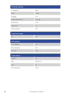
Page 53: ... Start Delay 1 0 S Intermittents Test For Duration Intermittents Test Duration 2 S Enter Lot ID OFF External Start Switch OFF External Safety Switch OFF LV Settings Connection Resistance 10 0 ohm LV Insulation Resistance 100 k ohm High Voltage 4250 only High Voltage ON HV Basic Settings High Voltage 50 V Insulation Resistance 5 M ohms Dwell Time 2 mS HV Advanced Settings DW Voltage 50 V DW Max Cur...

Page 54: ... 1 Cycle IR Voltage 50 V IR Minimum Resistance 50 M ohm IR Dwell Time 2 mS IR Soak Time 0 S Soak Until Good OFF Components Settings All OFF Data Collection Data Collection OFF Measured Values OFF Error Text OFF System Settings Volume 20 Date MM_DD_YY Time 24 Mains Frequency 60 Hz ...

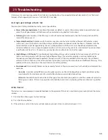
Page 55: ... Cirris for repair High Voltage 4250 only To troubleshoot a high voltage failure such as a dielectric failure remove the DUT and Learn a new test program with the same high voltage settings The tester may display a warning indicating no connections are found Proceed to perform the Learn and test If the same dielectric failure occurs the problem is either with the test fixture or the tester interfa...

Page 56: ...to move and flex the cable searching for intermittent errors Insulation Resistance IR The test applies a voltage and measures the current to determine if the resistance of the insulation is high enough Had Leakage error Occurs because more current than is acceptable leaks between unconnected points Learn The process of the tester scanning a known good cable to create a test program Low Voltage Tes...

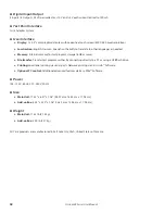
Page 57: ...istors 0 1 Ω to 100k Ω 1 0 1 Ω 100 kΩ to 5 MΩ 10 Capacitors 5 nF to 100 μF 10 0 02 nF Twisted Pairs Verify proper pairing in twisted pair cables High Voltage Test 4250 only Insulation Resistance Test Voltage 50 to 1500 VDC 5 5 V 2000 VDC optional Resistance 5M Ω to 1000 MΩ 10 Dielectric Withstand Test Voltage 50 to 150 VDC 5 5 V 2000 VDC optional 50 to 1000 VAC optional Current Limit 0 1 mA to 1 5...

Page 58: ...or test program storage 8 GB or more File transfer Transfer test programs either by connecting directly to a PC or using a USB flash drive Printing Local label printing via serial ports Network printing via Cirris Hub Software Optional PC control Additional advanced features via Easy Wire Software Power 105 135 V 60 Hz 210 260 V 50 Hz Size Main Unit 17 35 x 6 47 x 7 08 44 07 cm x 16 43 cm x 17 98 ...

Page 59: ...Specifications 59 ...

Page 60: ...Cirris 4200 Series User Manual Version 2019 2 1 2018 Cirris Systems Corporation 401 North 5600 West Salt Lake City Utah 84116 U S A www cirris com ...

Reviews: