background image

CDB8420

DS245DB4

7

3.2

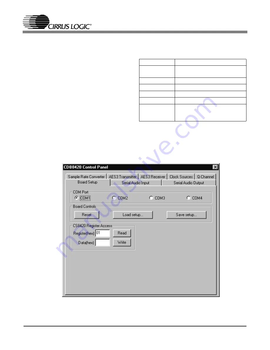
Board Setup

The Board Setup panel has some very useful func-
tions, including setting the COM Port used by the
application, resetting the CS8420 by the software,
as well as loading/saving register settings into files.
You can also can read or write any register on the
CS8420 using the CS8420 Register Access.

3.3

Script file syntax

The setup files generated by the board setup func-
tion only record the state of the chip registers.
There are many more useful commands that you
can insert into the setup scripts.  Here is a short de-
scription of them with their allowed syntax.

NOTE: Most commands accept either hexadecimal
(indicated by either a "0x" prefix or "h" suffix) or
decimal parameters.

Figure 2.  Board Setup Panel

//

used for single line comments

script scriptfile

call an external script file named 
"scriptfile"

reset 1

assert reset of the CS8420

reset 0

de-assert reset of the CS8420

wr 1 30h

write register 1 with hex 30

set DITH 1

set the bit field labeled DITH to 1

write 2 3 0x10 
12h 13

write 3 consecutive registers start-
ing from register 2 with hex 10, hex 
12, and decimal 13

Table 3. Script file syntax description

Summary of Contents for CDB8420

Page 1: ... to allow rapid evaluation of the CS8420 Because of the high performance of the CS8420 the board is set up for easy connection to an Audio Precision or a Rohde and Schwarz test system Currently available A D and D A converters are not ade quate to test the full performance of the device Input and output data may independently be set to either AES EBU or S PDIF in optical or coaxial physical format...

Page 2: ...up the Hardware 5 3 CDB8420 EXE USER S GUIDE 6 3 1 Main Window 6 3 2 Board Setup 7 3 3 Script file syntax 7 LIST OF FIGURES Figure 1 CDB8420 Control Panel Main Window 6 Figure 2 Board Setup Panel 7 Figure 3 CS8420 Sample Rate Converter 8 Figure 4 Atmel AVR RISC Micro controller 9 Figure 5 Power Supplies and Reset Circuit 10 Figure 6 Silkscreen 11 Figure 7 Top PCB 12 Figure 8 Bottom PCB 13 LIST OF ...

Page 3: ...el micro controller are available at http www atmel com 1 3 Crystal Oscillators There are two crystal oscillators on the board both are mounted in pin sockets that allow them to be re placed The oscillator labeled U10 provides the 6 MHz clock for the micro controller and should not be changed U3 is the oscillator that provides the Output Master Clock for the CS8420 The board is shipped with a 12 2...

Page 4: ...µC J10 Input Output 12 pin header for CS8420 control by external µC Table 1 System Connections JUMPER PURPOSE POSITION FUNCTION SELECTED J11 Selects physical format of digital audio interface input AES3 S PDIF OPTICAL Specifies input as either AES3 or S PDIF type Specifies input as OPTICAL type J12 Enables AES3 INPUT ENABLE DISABLE AES3 INPUT enabled AES3 INPUT disabled J13 Enables S PDIF INPUT EN...

Page 5: ...e 2 3 Starting up the software 1 Double click on CDB8420 exe or its shortcut 2 If you get errors right away the COM port needs to be set properly 3 Click anywhere but inside one of the boxes this brings up the Board Setup control panel 4 Select the COM port you are using to connect to the CDB8420 5 Shut down the application reset the board and then restart the application 2 4 Starting up the Hardw...

Page 6: ...es and formatting options To access additional details about each block click the left mouse button on the desired block This will display a control panel for the selected block If you click outside the boxes you will bring up the Board Setup control panel as shown on the next page Note that you can click on any of the tabs to quickly access that section Also any changes you make in the panel are ...

Page 7: ...ore useful commands that you can insert into the setup scripts Here is a short de scription of them with their allowed syntax NOTE Most commands accept either hexadecimal indicated by either a 0x prefix or h suffix or decimal parameters Figure 2 Board Setup Panel used for single line comments script scriptfile call an external script file named scriptfile reset 1 assert reset of the CS8420 reset 0...

Page 8: ...OLRCK INT U OMCK GND VD H S TXN TXP CDIN CCLK R9 47K C6 1uF OPT2 1 2 3 4 5 6 J2 PHONO JACK R18 681 R16 110 R14 6 2K C5 1uF C3 1uF T2 TRANSFORMER 1 8 4 5 6 2 C14 1uF 50V C15 1uF 50V R8 47K R7 47K C13 1uF 50V R6 47K R5 47K J4 XLR MALE 3 1 2 R2 47K R4 47K R3 47K C17 1uF U3 12 888MHz 1 7 8 14 NC GND Out VD R1 47K C16 1000pF R24 2 Ohms R13 47K R12 47K J5 HDR4X2 1 3 2 4 5 6 7 8 R11 47K C7 1000pF C10 1uF...

Page 9: ... 11 12 R31 2 Ohms TP32 U5 74HC574 2 3 4 5 6 7 8 9 11 1 19 18 17 16 15 14 13 12 D1 D2 D3 D4 D5 D6 D7 D8 CLK OC Q1 Q2 Q3 Q4 Q5 Q6 Q7 Q8 U6 HM628512 1 2 3 4 5 6 7 8 9 10 11 12 13 14 15 17 18 19 20 21 22 23 24 25 26 27 28 29 30 31 A18 A16 A14 A12 A7 A6 A5 A4 A3 A2 A1 A0 D0 D1 D2 D3 D4 D5 D6 D7 CS A10 OE A11 A9 A8 A13 WE A17 A15 U8 ATmega103 1 2 3 4 5 6 7 8 9 10 11 12 13 14 15 16 17 18 19 20 21 22 23 2...

Page 10: ...Sheet of Semiconductor Products Division RST RESET PGM MRST VA VD VD VD VD U2B 74VHC125 5 6 4 C22 01uF R28 47K D11 BAT85 1 2 U2C 74VHC125 9 8 10 R29 825 D4 LED_R 2 1 C19 1uF C18 100uF 6 3V C20 100uF 6 3V C21 1uF D2 BAT85 1 2 S5 SW_MOM 1 3 5 R38 10K J8 BLACK 1 Z1 P6KE6 8A 1 2 J7 RED 1 D3 BAT85 1 2 L3 FERRITE BEAD R27 2 Ohms Figure 5 Power Supplies and Reset Circuit ...

Page 11: ...CDB8420 DS245DB4 11 Figure 6 Silkscreen ...

Page 12: ...CDB8420 12 DS245DB4 Figure 7 Top PCB ...

Page 13: ...CDB8420 DS245DB4 13 Figure 8 Bottom PCB ...

Page 14: ...etent authorities of the Japanese Government if any of the products or technologies described in this material and controlled under the Foreign Exchange and Foreign Trade Law is to be exported or taken out of Japan An export license and or quota needs to be obtained from the competent authorities of the Chinese Government if any of the products or technologies described in thismaterial is subject ...

Reviews: