


16
©
Copyright 2004 Cirrus Logic, Inc.
DS651UM21
Version 2.1
CobraNet Hardware User’s Manual
Synchronization
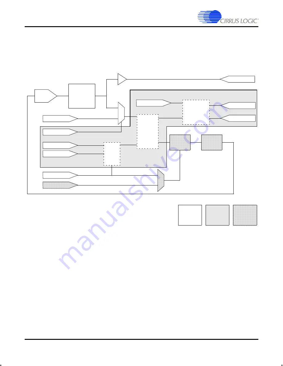
5.0 Synchronization
shows clock related circuits for the CS181xx and board design (CM-2). This
circuitry allows the synchronization modes documented below to be achieved. Modes are
distinguished by different settings of the multiplexors and software elements.
Figure 3. Audio Clock Sub-system
5.1
Synchronization Modes
Clock synchronization mode for conductor and performer roles is independently
selectable via management interface variables
syncConductorClock
and
syncPerformerClock
. The role (conductor or performer) is determined by the network
environment including the
conductor priority
setting of the device and the other devices on
the network. It is possible to ensure you will never assume the conductor role by selecting
a conductor priority of
zero
. However, it is not reasonable to assume that by setting a high
conductor priority, you will always assume the conductor role. For more information, refer
to CobraNet Programmer’s Reference Manual.
VCXO
24.576 MHz
±100 PPM
MCLK_OUT
MCLK_IN
MCLK_SEL
AClkConfig
Sample
Phase
Counter
Edge
Detect
RefClkEnable
RefClkPolarity
REFCLK
Phase
Detector
Loop
Filter
BeatReceived
Legend:
External
Software
Component
Hardware
Component
(CM2)
Internal
Hardware
Component
(CS181xx)
Audio
Clock
Generator
CS181xx
DAC
FS1
SCK


