


CobraNet Hardware User’s Manual
Mechanical Drawings and Schematics
DS651UM21
©
Copyright 2004 Cirrus Logic, Inc.
35
Version 2.1
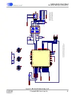
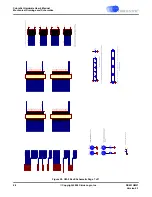
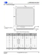
9.0 Mechanical Drawings and Schematics
The section contains detailed drawings of the CM-2 board and CS181xx device package
design. The mechanical drawings are arranged as follows:
•
"CM-2 Module Assembly Drawing" on page 36
•
"General PCB Dimensions" on page 37
•
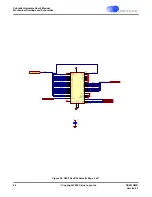
"Example Configuration, Side View" on page 38
•
"Faceplate Dimensions" on page 39
•
"Case Cutout for Faceplate Mounting" on page 40
•
•
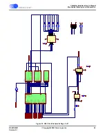
"CM-2 RevE Schematic Page 1 of 7" on page 42
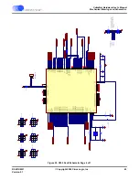
•
"CM-2 RevE Schematic Page 2 of 7" on page 43
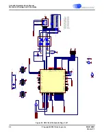
•
"CM-2 RevE Schematic Page 3 of 7" on page 44
•
"CM-2 RevE Schematic Page 4 of 7" on page 45
•
"CM-2 RevE Schematic Page 5 of 7" on page 46
•
"CM-2 RevE Schematic Page 6 of 7" on page 47
•
"CM-2 RevE Schematic Page 7 of 7" on page 48
•
"144-Pin LQFP Package Drawing" on page 49


