


CobraNet Hardware User’s Manual
Pinout and Signal Descriptions
DS651UM21
©
Copyright 2004 Cirrus Logic, Inc.
13
Version 2.1
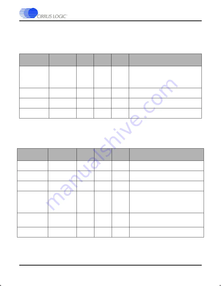
4.2.3 Synchronous Serial (Audio) Signals
The synchronous serial interfaces are used to bring digital audio into and out of the
system. Typically the synchronous serial is wired to ADCs and/or DACs. Detailed timing
and format is described in
"Digital Audio Interface" on page 19
.
4.2.4 Audio Clock Signals
See
for an overview of synchronization modes and issues.
*An external multiplexor controlled by this pin is required for full MCLK_IN and MCLK out
implementation.
Signal
Description
Direction
CM-2
Pin #
CS181xx
Pin #
Notes
DAO1_SCLK
Audio Bit Clock
Out
J3:A7
20
Synchronous serial bit clock.
64 FS for CS18100 (2x1 channel)
64 FS for CS18101 (2x4 channels)
128 FS for CS18102 (4x4 channels)
Typically tied to DAI1_SCLK.
DAO1_DATA[3:0]
Audio Output
Data
Out
J3:A18,
B18
15-17, 19
Output synchronous serial audio data
DAO1_DATA[3:1] not used for CS18100.
DAI1_DATA[3:0]
Audio Input Data
In
J3:
A[15:12]
131, 132,
134, 135
Input synchronous serial audio data
DAI1_DATA[3:1] not used for CS18100.
DAI1_SCLK
Audio Bit Clock
In
J4:A7
137
Should be tied to DAO1_SCLK.
Synchronous serial bit clock.
Signal
Description
Direction
CM-2
Pin #
CS181xx
Pin #
Notes
DAI1_LRCLK
Sample clock
input
In
138
Should be tied to DAO1_LRCLK for all devices.
DAO1_LRCLK
(FS1)
Sample clock
output
Out
J3:A3
22
FS1 (word clock) for CS18100 and CS18101.
DAO2_LRCLK
(FS1)
Sample clock
output
Out
J3:A3
14
FS1 (word clock) for CS18102.
REFCLK_IN
Reference clock
In
J3:A6
97
Clock input for synchronizing network to an
external clock source, for redundancy control and
synchronization of FS divider chain to external
source. See
for
more detail.
MCLK_IN
Master audio
clock input
In
J3:A5
8*
For systems featuring multiple CobraNet
interfaces operating off a common master clock.
See
for more detail.
MCLK_OUT
Master audio
clock output
Out
J3:A4
8*
Low jitter 24.576 MHz master audio clock.


