35
CS42426
5.5.2
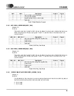
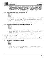
ADC ONE_LINE MODE (ADC_OLX)
Default = 00
Function:
These bits select which mode the ADC will use. By default one-line mode is disabled but can be se-
lected using these bits. Please see Figures 10 and 11 to see the format of one-line mode 1 and
one-line mode 2.
5.5.3
DAC ONE_LINE MODE (DAC_OLX)
Default = 00
Function:
These bits select which mode the DAC will use. By default one-line mode is disabled but can be se-
lected using these bits. Please see Figures 10 and 11 to see the format of one-line mode 1 and
one-line mode 2.
5.5.4
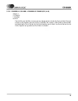
CODEC RIGHT JUSTIFIED BITS (CODEC_RJ16)
Default = 0
Function:
This bit determines how many bits to use during right justified mode for the DAC and ADC. By default
the DAC and ADC will be in RJ24 bits but can be set to RJ16 bits.
0 - 24 bit mode.
1 - 16 bit mode.
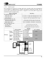
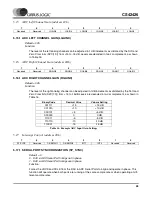
DIF1
DIF0
Description
Format
Figure
0
0
Left Justified, up to 24-bit data
0
0
1
I
2
S, up to 24-bit data
1
1
0
Right Justified, 16-bit or 24-bit data
2
1
1
reserved
-
-
Table 7. Digital Interface Formats
ADC_OL1
ADC_OL2
Description
Format
Figure
0
0
DIF: take the DIF setting from reg04h[7:6]
-
-
0
1
One-Line #1
3
1
0
One-Line #2
4
1
1
reserved
-
-
Table 8. ADC One_Line Mode
DAC_OL1
DAC_OL2
Description
Format
Figure
0
0
DIF: take the DIF setting from reg04h[7:6]
-
-
0
1
One-Line #1
3
1
0
One-Line #2
4
1
1
reserved
-
-
Table 9. DAC One_Line Mode


