CS42426
52
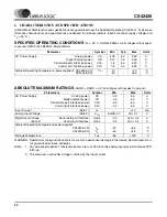
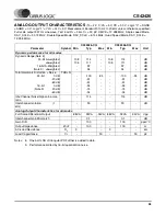
Notes: 3. Typical performance numbers are taken at 25° C. Min/Max performance numbers are guaranteed across
the specified temperature range, T
A
.
4. Referred to the typical full-scale voltage.
5. Measured between AIN+ and AIN-
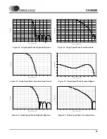
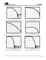
A/D DIGITAL FILTER CHARACTERISTICS
Notes: 6. The filter frequency response scales precisely with Fs.
7. Response shown is for Fs equal to 48 kHz. Filter characteristics scale with Fs.
FILT+ Nominal Voltage
Output Impedance
Maximum allowable DC current
-
-
-
5.0
35
0.01
-
-
-
-
-
-
5.0
35
0.01
-
-
-
V
k
Ω
mA
Parameter
Symbol
Min
Typ
Max
Unit
Single Speed Mode (2 to 50 kHz sample rates)
Passband
(-0.1 dB)
(Note 6)
0
-
0.47
Fs
Passband Ripple
-
-
±
0.035
dB
Stopband (Note
6)
0.58
-
-
Fs
Stopband Attenuation
-95
-
-
dB
Total Group Delay (Fs = Output Sample Rate)
t
gd
-
12/Fs
-
s
Group Delay Variation vs. Frequency
∆
t
gd
-
-
0.0
µ
s
Double Speed Mode (50 to 100 kHz sample rates)
Passband
(-0.1 dB)
(Note 6)
0
-
0.45
Fs
Passband Ripple
-
-
±
0.035
dB
Stopband
(Note 6)
0.68
-
-
Fs
Stopband Attenuation
-92
-
-
dB
Total Group Delay (Fs = Output Sample Rate)
t
gd
-
9/Fs
-
s
Group Delay Variation vs. Frequency
∆
t
gd
-
-
0.0
µ
s
Quad Speed Mode (100 to 192 kHz sample rates)
Passband
(-0.1 dB)
(Note 6)
0
-
0.24
Fs
Passband Ripple
-
-
±
0.035
dB
Stopband
(Note 6)
0.78
-
-
Fs
Stopband Attenuation
-97
-
-
dB
Total Group Delay (Fs = Output Sample Rate)
t
gd
-
5/Fs
-
s
Group Delay Variation vs. Frequency
∆
t
gd
-
-
0.0
µ
s
High Pass Filter Characteristics
Frequency Response
-3.0 dB
-0.13 dB
(Note 7)
-
1
20
-
-
Hz
Hz
Phase Deviation
@ 20 Hz
(Note 7)
-
10
-
Deg
Passband Ripple
-
-
0
dB
Filter Setting Time
-
10
5
/Fs
-
s

