DS726PP2
15
CS4525
4. TYPICAL SYSTEM CONFIGURATION DIAGRAMS
Main Tuner
A/V Switch
PIP Tuner
A/V In 1
A/V In 2
A/V In X
Audio
Delay
27 MHz
Crystal In
Crystal Out
2 x 7 W 1 x 15 W Subwoofer
Clock
Out
Control Port
MPEG
Decoder
CS4525
PWM_SIG1
PWM_SIG2
Power
Foldback
Aux
Out
Analog In
Digital In
Delay
Port
Gate
Drive
Gate
Drive
Gate
Drive
Gate
Drive
SYS_CLK
Control
Port
Digital Out
Monitor Out
HP/
Line
Out
Left
Speaker
Right
Speaker
Subwoofer
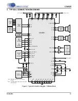
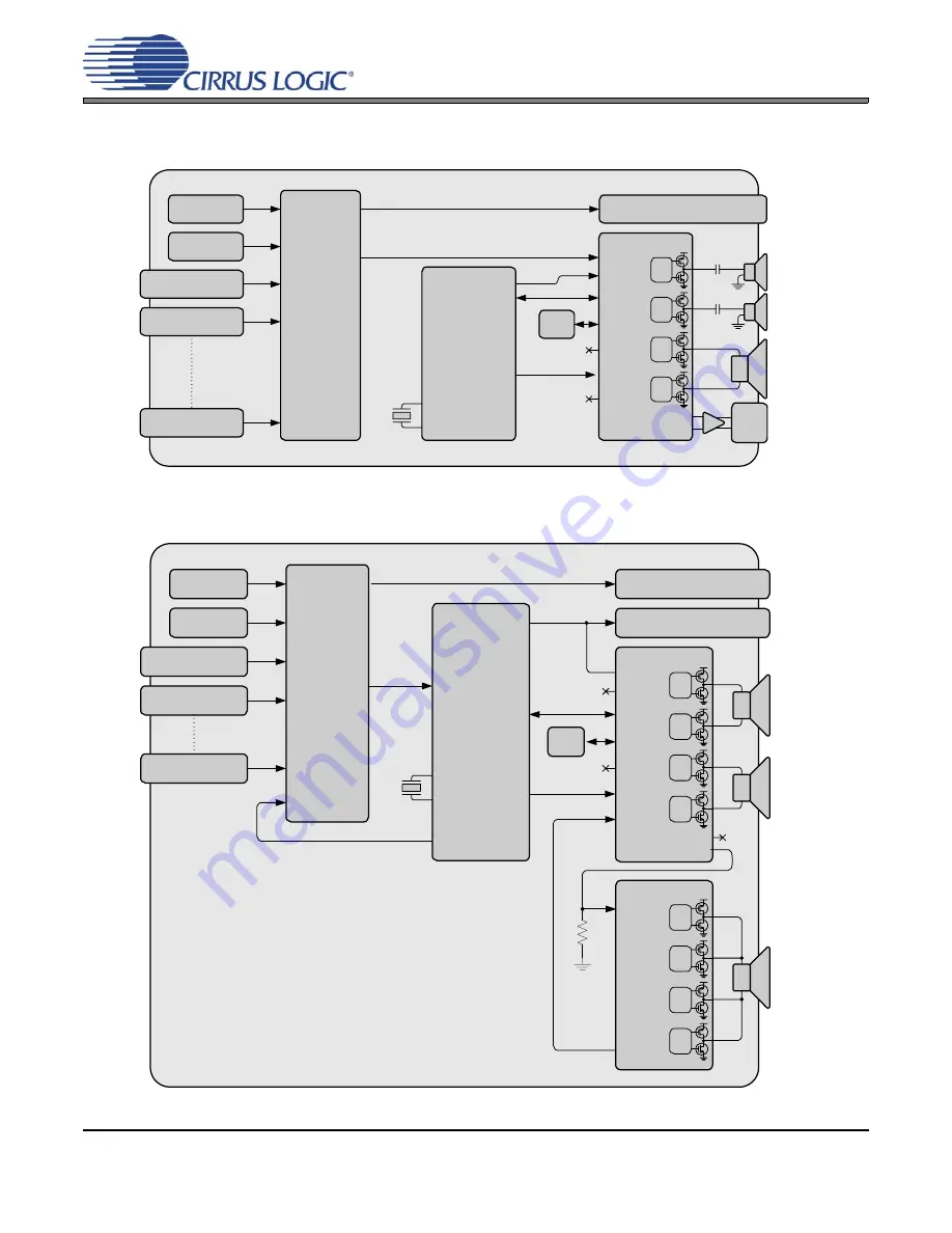
Figure 3. Typical System Configuration 1
Main Tuner
A/V Switch
PIP Tuner
A/V In 1
A/V In 2
A/V In X
Monitor Out
Audio
Delay
Analog
Out
Analog
In
Analog
Out
27 MHz
Crystal In
Crystal Out
CS4525
PWM_SIG1
PWM_SIG2
Gate
Drive
Gate
Drive
Gate
Drive
Gate
Drive
CS4412A
PWM In
Status
Out
Subwoofer
2 x 15 W 1 x 30 W Subwoofer
Power
Foldback
Aux
Out
Analog In
Digital In
Delay
Port
Gate
Drive
Gate
Drive
Gate
Drive
Gate
Drive
Clock
Out
SYS_CLK
Control
Port
Control
Port
Sound
Processor
Var/Fixed Out
Left
Speaker
Right
Speaker
22 k
Ω
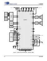
Figure 4. Typical System Configuration 2


