DS726PP2
21
CS4525
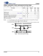
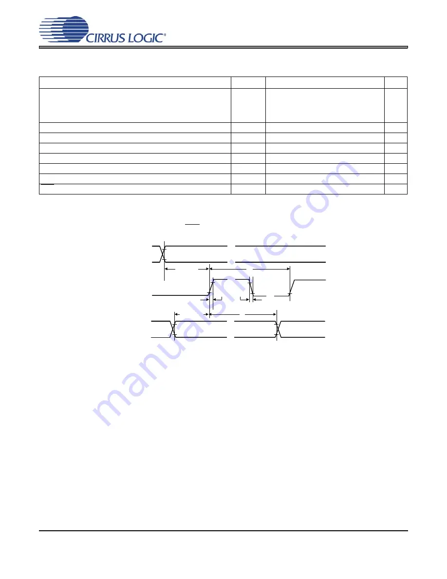
SERIAL AUDIO INPUT PORT SWITCHING SPECIFICATIONS
AGND = DGND = PGND = 0 V; T
A
= 25°C; VD = 3.3 V; Inputs: Logic 0 = DGND; Logic 1 = VD.
Notes:
8.
F
CLK
is the frequency of the crystal connected to the XTI/XTO pins or the input SYS_CLK signal.
9.
N
bits
is the number of bits per sample of the serial digital input.
10. After powering up the CS4525, RST should be held low until the power supplies and clocks are stable.
Parameters
Symbol Min Nominal
Max
Units
Supported Input Sample Rates
F
SI
28.5
39.5
39.5
86.4
32
44.1
48
96
35.2
52.8
52.8
105.6
kHz
kHz
kHz
kHz
LRCK Duty Cycle
45
-
55
%
SCLK Frequency
1/t
p
F
SI
*2*N
bits
-
F
CLK
/3
Hz
SCLK Duty Cycle
45
-
55
%
LRCK Setup Time Before SCLK Rising Edge
t
s(LK-SK)
40
-
-
ns
SDIN Setup Time Before SCLK Rising Edge
t
s(SD-SK)
25
-
-
ns
SDIN Hold Time After SCLK Rising Edge
t
h
10
-
-
ns
RST pin Low Pulse Width
1
-
-
ms
//
//
//
//
//
//
t
s(SD-SK)
MSB
MSB-1
LRCK
SCLK
SDIN
t
r
t
f
t
s(LK-SK)
t
P
t
h
Figure 7. Serial Audio Input Port Timing

