52
DS726PP2
CS4525
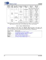
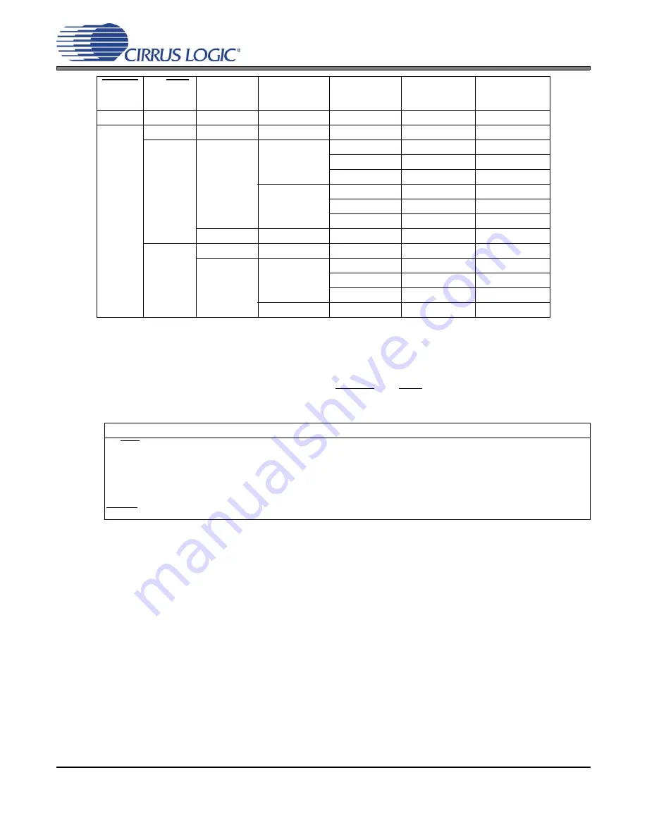
Table 12. Output of PWM_SIG Outputs
describes the exact output of the PWM_SIG output pins based on the input to the
HP_DETECT/MUTE pin and the settings of the HiZPSig, HP/Mute, BassMgr[2:0], and PWMDSel[1:0]
bits. In all configurations, the active logic input level is determined by the HP/MutePol bit.
HiZPSig
Setting
HP/Mute
Setting
HP_DETECT
/MUTE Input
BassMgr [2:0]
Setting
PWMDSel [1:0]
Setting
PWM_SIG1
Output
PWM_SIG2
Output
0
X
X
X
X
High Impedance High Impedance
1
X
X
X
00 (Disabled)
Driven Low
Driven Low
0
(Mute
Mode)
Not Active
000
(Disabled)
01
Channel 1
Channel 2
10
Channel 1
Mute
11
Channel 2
Mute
001 through 111
01
Channel 1
Channel 2
10
Channel 1
Sub Channel
11
Channel 2
Sub Channel
Active
X
01, 10, or 11
Mute
Mute
1
(Head-
phone
Mode)
Not Active
X
01, 10, or 11
Mute
Mute
Active
000
(Disabled)
01
Channel 1*
Channel 2**
10
Channel 1*
Mute
11
Channel 2**
Mute
001 through 111
01, 10, or 11
Channel 1*
Channel 2**
*Signals denoted with one asterisk do not have Bass Manager, 2-Way Crossover, or Channel Mix applied.
**Signals denoted with two asterisks do not have Bass Manager or 2-Way Crossover applied.
Referenced Control
Register Location
HP/Mute ..............................
“HP_Detect/Mute Pin Mode (HP/Mute)” on page 70
HP/MutePol .........................
“HP_Detect/Mute Pin Active Logic Level (HP/MutePol)” on page 70
PWMDSel[1:0].....................
“PWM Signals Output Data Select (PWMDSel[1:0])” on page 73
LChMix[1:0] .........................
“Left Channel Mixer (LChMix[1:0])” on page 76
RChMix[1:0] ........................
“Right Channel Mixer (RChMix[1:0])” on page 76
En2Way...............................
“Enable 2-Way Crossover (En2Way)” on page 81
BassMgr[2:0] .......................
“Bass Cross-Over Frequency (BassMgr[2:0])” on page 79
HiZPSig ...............................


