DS726PP2
59
CS4525
6.4
Output Filters
The filter placed after the PWM outputs can greatly affect the output performance. The filter not only reduces
radiated EMI (snubber filter), but also filters high frequency content from the switching output before going
to the speaker (low-pass LC filter).
6.4.1
Half-Bridge Output Filter
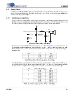
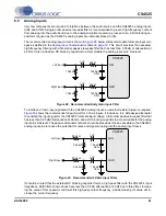
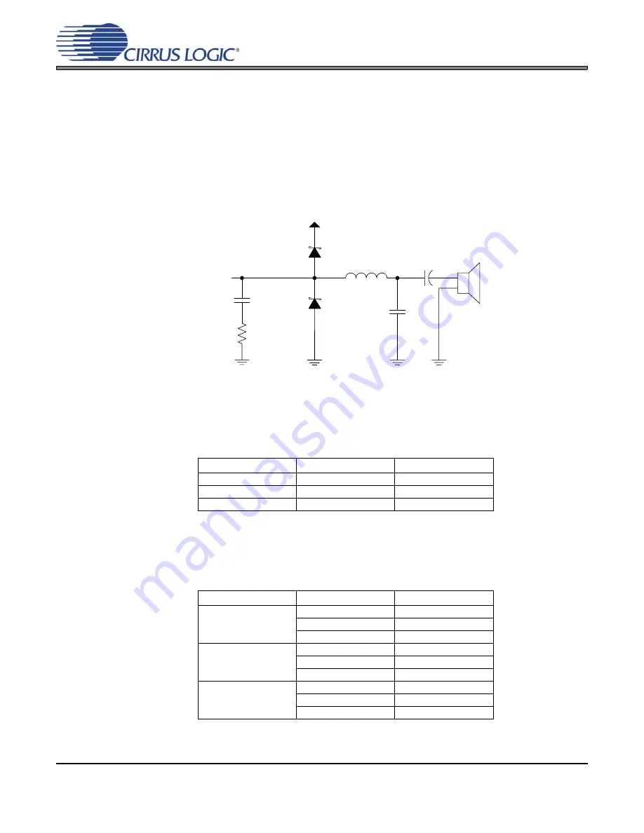
shows the output filter for a half-bridge configuration. The transient-voltage suppression circuit
(snubber circuit) is comprised of a capacitor (680 pF) and a resistor (5.6
Ω
, 1/8 W) and should be placed
as close as possible to the corresponding PWM output pin to greatly reduce radiated EMI.
The inductor, L1, and capacitor, C1, comprise the low-pass filter. Along with the nominal load impedance
of the speaker, these values set the cutoff frequency of the filter.
shows the component values
for L1 and C1 based on nominal speaker (load) impedance for a corner frequency (-3 dB point) of approx-
imately 35 kHz.
C2 is the DC-blocking capacitor.
shows the component values for C2 based on corner frequency
(-3 dB point) and a nominal speaker (load) impedances of 4
Ω,
6
Ω,
and
8
Ω
. This capacitor should also
be chosen to have a ripple current rating above the amount of current that will passed through it.
Load
L1
C1
4
Ω
22 µH
1.0 µF
6
Ω
33 µH
0.68 µF
8
Ω
47 µH
0.47 µF
Table 18. Low-Pass Filter Components - Half-Bridge
Load
Corner Frequency
C2
4
Ω
40 Hz
1000 µF
58 Hz
680 µF
120 Hz
330 µF
6
Ω
39 Hz
680 µF
68 Hz
390 µF
120 Hz
220 µF
8
Ω
42 Hz
470 µF
60 Hz
330 µF
110 Hz
180 µF
Table 19. DC-Blocking Capacitors Values - Half-Bridge
OUTx
680 pF
C1
5.6
Ω
L1
C2
+
-
VP
*Diode is Rohm
RB160M-30 or
equivalent
Figure 26. Output Filter - Half-Bridge

