84
DS726PP2
CS4525
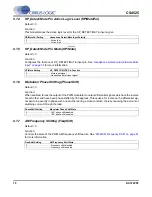
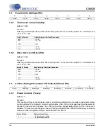
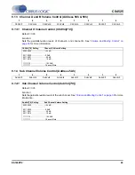
9.15
Mute/Invert Control (Address 5Bh)
9.15.1
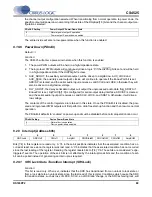
ADC Invert Signal Polarity (InvADC)
Default = 0
Function:
When set, the signal polarity of the ADC will be inverted.
9.15.2
Invert Channel PWM Signal Polarity (InvChX)
Default = 0
Function:
When set, the respective channel’s power and logic-level PWM output signal polarity will be inverted. The
serial output on the auxiliary and delay ports are unaffected.
9.15.3
Invert Sub PWM Signal Polarity (InvSub)
Default = 0
Function:
When set, the Sub channel’s power and logic-level PWM output polarity will be inverted. The serial output
on the auxiliary port is unaffected.
9.15.4
ADC Channel Mute (MuteADC)
Default = 0
Function:
The output of the ADC will mute when enabled.
9.15.5
Independent Channel A & B Mute (MuteChX)
Default = 0
Function:
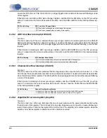
The respective channel’s power PWM, logic-level PWM, and auxiliary serial data outputs will enter a mute
state when enabled. The delay serial output will be unaffected if the delay port is enabled. The muting
7
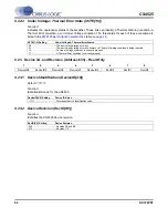
6
5
4
3
2
1
0
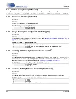
InvADC
InvSub
InvCh2
InvCh1
MuteADC
MuteSub
MuteChB
MuteChA
InvADC Setting
ADC Signal Inversion State
0 .......................................... ADC signal polarity not inverted.
1 .......................................... ADC signal polarity inverted.
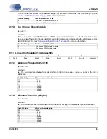
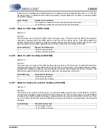
InvChX Setting
Channel X PWM Signal Inversion State
0 .......................................... Channel X PWM signal polarity not inverted.
1 .......................................... Channel X PWM signal polarity inverted.
InvSub Setting
Sub Channel PWM Signal Inversion State
0 .......................................... Sub channel PWM signal polarity not inverted.
1 .......................................... Sub channel PWM signal polarity inverted.
MuteADC Setting
ADC Mute State
0 .......................................... ADC un-muted.
1 .......................................... ADC muted.

