Serial Control Port Configuration
CS485xx Hardware User’s Manual
DS734UM7
Copyright 2009 Cirrus Logic, Inc.
3-8
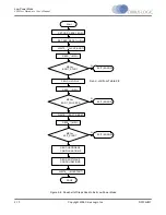
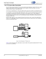
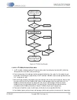
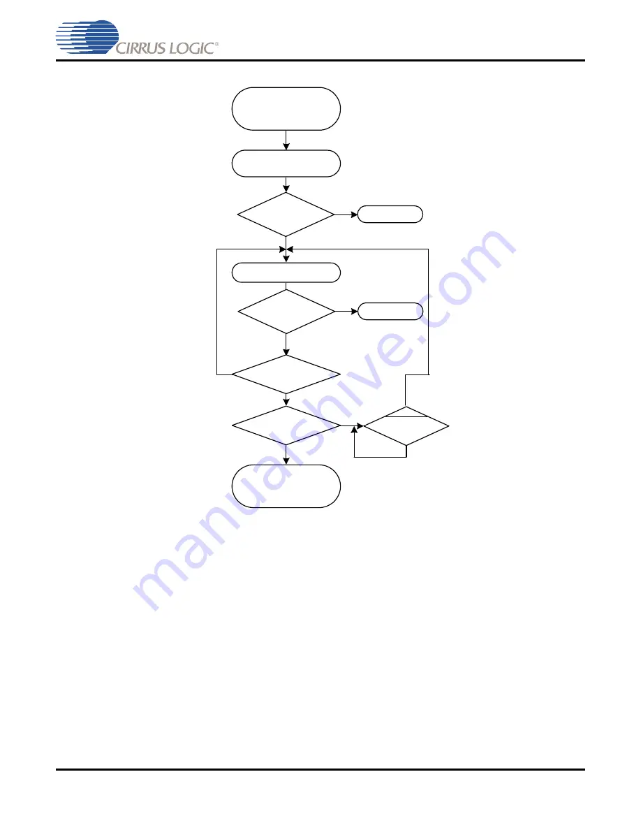
Figure 3-8. I
2
C Write Flow Diagram
3.2.2.3.1 I
2
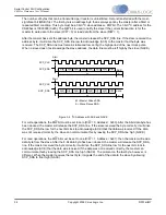
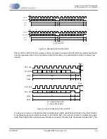
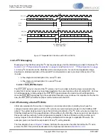
C Write Protocol Procedure
1. An I
2
C transfer is initiated with an I
2
C start condition which is defined as the data (SCP_SDA) line
falling while the clock (SCP_CLK) is held high.
2. This is followed by a 7-bit address and the read/write bit held low for a write. So, the master should
send 0x80. The 0x80 byte represents the 7-bit I
2
C address 1000000b, and the least significant bit set
to ‘0’, designates a write.
3. After each byte (including the address and each data byte) the master must release the data line and
provide a ninth clock for the CS485xx DSP (slave) to acknowledge (ACK) receipt of the byte. The
CS485xx will drive the data line low during the ninth clock to acknowledge. If for some reason
CS485xx does not acknowledge (NACK), it means that the communications channel has been
corrupted and the CS485xx should be re-booted. A NACK should never happen here.
4. The master should then clock one data byte into the device, most-significant bit first.
5. The CS485xx (slave) will (and must) acknowledge (ACK) each byte that it receives which means that
MORE DATA?
SEND I2C START:
DRIVE SCP_SDA LOW
WHILE SCP_CLK IS
HIGH
WRITE ADDRESS BYTE
0x80
N
SEND DATABYTE
I2C STOP:
DRIVE SCP_SDA HIGH
WHILE SCP_CLK IS
HIGH
Y
SCP_BSY
(LOW)?
N
Y
Y
N
4 BYTES SENT?
SCP_SDA ==
ACK?
Y
N
EXIT (ERROR)
SCP_SDA ==
ACK?
Y
N
EXIT (ERROR)

