


DS734UM7
Copyright 2009 Cirrus Logic
v
Figures
CS485xx Hardware User’s Manual
Figures
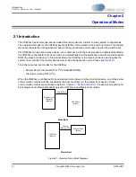
Figure 3-2. Block Diagram of I
2
C System Bus .............................................................................................3-3
C Start and Stop Conditions ....................................................................................................3-4
C Address with ACK and NACK ..............................................................................................3-5
C Write Flow Diagram .............................................................................................................3-8
C Read Flow Diagram ...........................................................................................................3-10
Figure 3-10. Sample Waveform for I
2
C Write Functional TIming ...............................................................3-12
Figure 3-11. Sample Waveform for I
2
C Read Functional Timing ...............................................................3-12


