CDB4923 CDB49300
DS262DB2
39
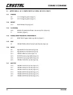
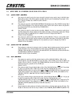
12. APPENDIX F: BOARD CONTROL SOFTWARE
There is a suite of programs used to control the
CDB4923/300. The definitions given refer to
‘CDB30’ executables which should be used with
the both the CDB4923 and the CDB300.
These software tools are designed to operate from
a DOS prompt and can work with any parallel port
address (LPT1, LPT2, or LPT3). The default ad-
dress for all of the programs is 0x378 (also known
as LPT1), but the port address can be changed by
using the '-p' option provided with every tool. Each
time a program is executed, the address that was
used is echoed to the screen. If a program seems to
fail, verification of the parallel port address should
the first step in troubleshooting.
All of these programs are designed to access the
CS492x/CS493xx using SPI or I2C serial commu-
nication, or INTEL or MOTOROLA parallel com-
munication. The communication mode can be
chosen from the command line with the '-m' option.
It should be remembered that the mode chosen
must correspond to the communication mode used
by the CS492x/CS493xx. If the DSP is using a
communication mode which does not match the
software setting, results will be unpredictable.
Please see Digital Signal Processor of this
datasheet to learn how to change the DSP’s com-
munication mode.
The source code for all programs can be found on
the floppy disk provided with the CDB4923/300.
These programs are documented and will provide
insight into communicating successfully with the
CS492x/CS493xx. The source for CDB30_LD is
particularly useful since it demonstrates the full
handshaking protocol required during boot-up of
the CS492x/CS493xx.
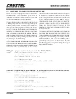
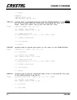
CDB30_LD - program used to load code into the CS492x/CS493xx.
Usage:
cdb30_ld <input_file.ld> [-pXXX] [-mY] [-v]
-p = parallel port address
XXX = address (0x278, 378* or 3bc)
-m = communication mode
Y = mode designator (i = I2C*, s=SPI, m=MOT, n=INT)
-v = disable verbose mode
* = default
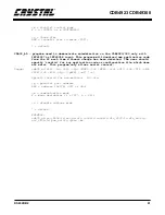
CDB30CMD - program used to send commands, or configuration files to the CS492x/CS493xx.
Usage:
cdb30cmd <[ABCDEF] or [-fY]> [-mZ] [-pXXX] [-v]
ABCDEF = Three byte hex command
-f = send configuration file
Y = .cfg file with configuration parameters
-p = parallel port address
XXX = address (0x278, 378* or 3bc)
-m = communication mode
Z = mode designator (i = I2C*, s = SPI, m=MOT, n=INT)
-v = disable verbose mode
Summary of Contents for CS492 Series
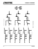
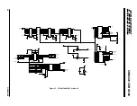
Page 18: ...CDB4923 CDB49300 18 DS262DB2 9 APPENDIX A SCHEMATICS Figure 4 CS492x CS493xx ...
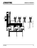
Page 19: ...CDB4923 CDB49300 DS262DB2 19 Figure 5 System Power ...
Page 20: ...CDB4923 CDB49300 20 DS262DB2 Figure 6 PC Interface ...
Page 21: ...CDB4923 CDB49300 DS262DB2 21 Figure 7 Control Logic ...
Page 22: ...CDB4923 CDB49300 22 DS262DB2 Figure 8 Clocking ...
Page 23: ...CDB4923 CDB49300 DS262DB2 23 Figure 9 Analog Input ...
Page 24: ...CDB4923 CDB49300 24 DS262DB2 Figure 10 Digital Input ...
Page 25: ...CDB4923 CDB49300 DS262DB2 25 Figure 11 D A Converters ...
Page 26: ...CDB4923 CDB49300 26 DS262DB2 Figure 12 Analog Output ...
Page 27: ...CDB4923 CDB49300 DS262DB2 27 Figure 13 Digital Output ...
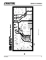
Page 28: ...CDB4923 CDB49300 28 DS262DB2 Figure 14 Top Layer ...
Page 29: ...CDB4923 CDB49300 DS262DB2 29 Figure 15 Bottom Layer ...
Page 30: ...CDB4923 CDB49300 30 DS262DB2 Figure 16 SSTOP ...
Page 31: ...CDB4923 CDB49300 DS262DB2 31 Figure 17 ASYSTOP ...
Page 32: ...CDB4923 CDB49300 32 DS262DB2 Figure 18 Layer 2 ...
Page 33: ...CDB4923 CDB49300 DS262DB2 33 Figure 19 Layer 3 ...
Page 49: ... Notes ...
Page 50: ......


