DS785UM1
6-1
Copyright 2007 Cirrus Logic
6
6
6
Chapter 6
6
Vectored Interrupt Controller
6.1 Introduction
The EP93xx processors contain two cascaded Vectored Interrupt Controllers (VIC). A
Vectored Interrupt has improved latency compared with a simple interrupt controller, since it
provides direct information about where the interrupt’s service routine is located and
eliminates levels of software arbitration.
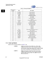
Each individual Vectored Interrupt Controller can handle up to 32 interrupts, but there are
more than 32 interrupts in this design. Therefore two VICs are connected in a daisy-chain,
which allows the system to handle up to 64 interrupt sources.
There are up to 16 vectored interrupts and 16 non-vectored interrupts available on each VIC.
Vectored interrupts can only generate an IRQ interrupt. Non-vectored interrupts can generate
either an IRQ interrupt or a FIQ interrupts. Vectored Interrupt Requests (IRQ) provide an
address for an Interrupt Service Routine (ISR). Reading from the vector interrupt address
register,
, provides the address of the ISR, and indicates to the interrupt priority
hardware that the interrupt is being serviced. Writing to the
register indicates
to the interrupt priority hardware that the interrupt has been serviced, allowing lower priority
interrupts to go active.
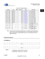
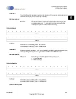
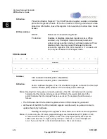
Registers in the VIC use a bit position for each different interrupt source. The bit position is
fixed, but the handling of each interrupt is configurable by the VIC. Software can generate
software interrupts by controlling each request line.
The VIC provides a software interface to the interrupt system. Two levels of interrupts are
available:
•
Fast Interrupt Request (FIQ) for fast, low latency interrupt handling
•
Interrupt Request (IRQ) for more general interrupts
All interrupt inputs to the VIC are presented as active-high level sensitive signals. Any
conditioning needed to achieve this is performed by the block generating the interrupt
request. In the case of external interrupts, the GPIO block takes care of the conditioning.
Note: Some GPIO signals are not configurable but are used as inputs by other functional
blocks. EGPIO[2:1] are routed to the DMA controller to allow for external DMA requests.
Note: An interrupt vector may be overwritten when two interrupts occur simultaneously. If a
VIC2 interrupt is immediately followed by a VIC1 interrupt, the VIC1 address will
incorrectly be the default handler address for 2 HCLK cycles. To work around this
problem, first check for pending non-vectored VIC1 interrupts in the interrupt routine. If
there are none then return from interrupt. The interrupt will immediately re-occur with the
correct vector address.
Summary of Contents for EP93 Series
Page 28: ...P 6 DS785UM1 Copyright 2007 Cirrus Logic Preface EP93xx User s Guide PP P ...
Page 162: ...5 36 DS785UM1 Copyright 2007 Cirrus Logic System Controller EP93xx User s Guide 55 5 ...
Page 576: ...15 18 DS785UM1 Copyright 2007 Cirrus Logic UART2 EP93xx User s Guide 1515 15 ...
Page 634: ...17 38 DS785UM1 Copyright 2007 Cirrus Logic IrDA EP93xx User s Guide 1717 17 ...
Page 648: ...19 6 DS785UM1 Copyright 2007 Cirrus Logic Watchdog Timer EP93xx User s Guide 1919 19 ...
Page 688: ...21 32 DS785UM1 Copyright 2007 Cirrus Logic I2S Controller EP93xx User s Guide 2121 21 ...
Page 790: ...27 20 DS785UM1 Copyright 2007 Cirrus Logic IDE Interface EP93xx User s Guide 2727 27 ...
Page 808: ...28 18 DS785UM1 Copyright 2007 Cirrus Logic GPIO Interface EP93xx User s Guide 2828 28 ...


