7-26
DS785UM1
Copyright 2007 Cirrus Logic
Raster Engine With Analog/LCD Integrated Timing and Interface
EP93xx User’s Guide
7
7
7
The X location value controls the starting horizontal X location of the cursor image. The value
is compared to the horizontal pixel counter and should be set by software to be between the
active start and active stop horizontal pixel values. The cursor hardware will clip the cursor at
the right edge of the screen. This value is also used to control the starting location for the
cursor image on the upper half of the screen during dual scan mode. To prevent cursor
distortion, the new X location value will not be used until the next frame.
During dual scan display mode, selected by writing DSCAN = ‘1’ to the
register,
the lower half Y value controls the starting vertical Y location on the lower half of the screen
for the cursor image. The value is compared to the vertical line counter and should be set by
software to be between the active start and active stop vertical line values. The cursor
hardware will clip the cursor at the bottom of the screen. To prevent cursor distortion, the new
location value will not be used until the next frame.
The hardware cursor circuitry has a separate blinking function. The rate is a 50% duty cycle
programmable number of vertical frame intervals. When a blink frame is active, the color
RGB mux switches in 24-bit
values for
or
respectively.
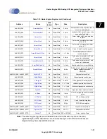
7.4.9.1 Registers Used for Cursor
The registers used for configuring the Hardware Cursor are:
,
and
. The following subsections describe the function of each of these
registers.
7.4.9.1.1 CursorAdrStart Register
This register contains the memory starting address for the cursor image.
7.4.9.1.2 CursorAdrReset Register
This register contains the address for the part of the cursor that is displayed next after
reaching the last line of the cursor. This register is needed to support DUAL scan displays.
For non-dual scan displays, this address is the same as that in the CursorAdrStart register.
7.4.9.1.3 CursorSize Register
This register selects four parameters that will impact the cursor size: CSTEP, CLINS, CWID,
and DLNS.
CSTEP
Two bits select the cursor step size:
0 0
Step by 1 word or 16 pixels
0 1
Step by 2 words or 32 pixels
1 0
Step by 3 words or 48 pixels
1 1
Step by 4 words or 64 pixels
Summary of Contents for EP93 Series
Page 28: ...P 6 DS785UM1 Copyright 2007 Cirrus Logic Preface EP93xx User s Guide PP P ...
Page 162: ...5 36 DS785UM1 Copyright 2007 Cirrus Logic System Controller EP93xx User s Guide 55 5 ...
Page 576: ...15 18 DS785UM1 Copyright 2007 Cirrus Logic UART2 EP93xx User s Guide 1515 15 ...
Page 634: ...17 38 DS785UM1 Copyright 2007 Cirrus Logic IrDA EP93xx User s Guide 1717 17 ...
Page 648: ...19 6 DS785UM1 Copyright 2007 Cirrus Logic Watchdog Timer EP93xx User s Guide 1919 19 ...
Page 688: ...21 32 DS785UM1 Copyright 2007 Cirrus Logic I2S Controller EP93xx User s Guide 2121 21 ...
Page 790: ...27 20 DS785UM1 Copyright 2007 Cirrus Logic IDE Interface EP93xx User s Guide 2727 27 ...
Page 808: ...28 18 DS785UM1 Copyright 2007 Cirrus Logic GPIO Interface EP93xx User s Guide 2828 28 ...

