11-4
DS785UM1
Copyright 2007 Cirrus Logic
Universal Serial Bus Host Controller
EP93xx User’s Guide
1
1
1
1
11
11.2.2.2 Data Structures
The basic building blocks for communication across the interface are the Endpoint Descriptor
(ED) and Transfer Descriptor (TD).
The Host Controller Driver assigns an Endpoint Descriptor to each endpoint in the system.
The Endpoint Descriptor contains the information necessary for the Host Controller to
communicate with the endpoint. The fields include the maximum packet size, the endpoint
address, the speed of the endpoint, and the direction of data flow. Endpoint Descriptors are
linked in a list.
A queue of Transfer Descriptors is linked to the Endpoint Descriptor for the specific endpoint.
The Transfer Descriptor contains the information necessary to describe the data packets to
be transferred. The fields include data toggle information, shared memory buffer location, and
completion status codes. Each Transfer Descriptor contains information that describes one or
more data packets. The data buffer for each Transfer Descriptor ranges in size from 0 to 8192
bytes with a maximum of one physical page crossing. Transfer Descriptors are linked in a
queue: the first one queued is the first one processed.
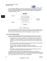
Each data transfer type has its own linked list of Endpoint Descriptors to be processed.
, Typical List Structure, is a representation of the data structure relationships.
Figure 11-3. Typical List Structure
The head pointers to the bulk and control Endpoint Descriptor lists are maintained within the
operational registers in the HC. The Host Controller Driver initializes these pointers prior to
the Host Controller gaining access to them. Should these pointers need to be updated, the
Host Controller Driver may need to halt the Host Controller from processing the specific list,
update the pointer, then re-enable the HC.
The head pointers to the interrupt Endpoint Descriptor lists are maintained within the HCCA.
There is no separate head pointer for isochronous transfers. The first isochronous Endpoint
Descriptor simply links to the last interrupt Endpoint Descriptor. There are 32 interrupt head
pointers. The head pointer used for a particular frame is determined by using the last 5 bits of
the Frame Counter as an offset into the interrupt array within the HCCA.
The interrupt Endpoint Descriptors are organized into a tree structure with the head pointers
being the leaf nodes. The desired polling rate of an Interrupt Endpoint is achieved by
Head Ptr
ED
ED
ED
ED
TD
TD
TD
TD
TD
TD
TD
Summary of Contents for EP93 Series
Page 28: ...P 6 DS785UM1 Copyright 2007 Cirrus Logic Preface EP93xx User s Guide PP P ...
Page 162: ...5 36 DS785UM1 Copyright 2007 Cirrus Logic System Controller EP93xx User s Guide 55 5 ...
Page 576: ...15 18 DS785UM1 Copyright 2007 Cirrus Logic UART2 EP93xx User s Guide 1515 15 ...
Page 634: ...17 38 DS785UM1 Copyright 2007 Cirrus Logic IrDA EP93xx User s Guide 1717 17 ...
Page 648: ...19 6 DS785UM1 Copyright 2007 Cirrus Logic Watchdog Timer EP93xx User s Guide 1919 19 ...
Page 688: ...21 32 DS785UM1 Copyright 2007 Cirrus Logic I2S Controller EP93xx User s Guide 2121 21 ...
Page 790: ...27 20 DS785UM1 Copyright 2007 Cirrus Logic IDE Interface EP93xx User s Guide 2727 27 ...
Page 808: ...28 18 DS785UM1 Copyright 2007 Cirrus Logic GPIO Interface EP93xx User s Guide 2828 28 ...


