12-2
DS785UM1
Copyright 2007 Cirrus Logic
Static Memory Controller
EP93xx User’s Guide
1
2
1
2
12
The SMC has five main functions:
1. Memory bank selecting
2. Access timing
3. Wait State generation
4. Byte lane write enabling
5. External bus interfacing
12.2 Static Memory Controller Operation
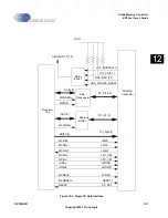
The SMC provides access to static memory devices that are attached to the external bus.
The SMC can work with a wide variety of external device types, including SRAM, ROM, NOR
FLASH, and peripherals that respond to SRAM-type signaling.
Six chip-select output signals, CSn7, CSn6, CSn3, CSn2,
CSn1, and
CSn0 can be used to
access six different memory spaces. However, only one of the six memory banks can be
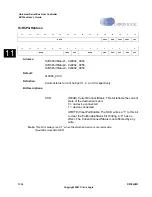
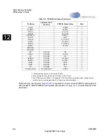
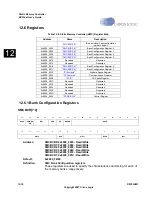
accessed at a given time. The SMC has six independent control registers that configure the
six respective chip-select signals. Each control register,
specifies the timing
characteristics that are needed to access the memory device(s) in its respective memory
space.
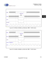
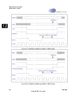
, the SMC captures read data on the HCLK edge
that occurs just prior to the HCLK edge that de-asserts the chip-select output signal on the
CSnX pin. The output signal on the CSnX pin and the address outputs on the AD[x] pins are
de-asserted on the next HCLK edge.
The SMC can insert wait cycles into its access timing. Wait cycles can be specified by:
•
A programmable value, N, where N has the range 1<N<32. When N is used, the SMC
holds its bus state for N HCLK cycles. The value for N must be written to the WST2
and/or WST1 fields of the
register(s).
•
An asserted wait input signal on the WAITn pin. As shown in
and
, the WAITn pin can be asserted as needed by an external device to extend access
time. When WAITn is asserted, the SMC holds its bus state until WAITn is sampled as
being de-asserted. For internal synchronization to occur,
WAITn
must remain asserted
for a minimum of two HCLK cycles.
•
When both N and
WAITn
are used, the SMC holds its bus state for N HCLK cycles or
until WAITn is sampled as being de-asserted, whichever occurs last.
Summary of Contents for EP93 Series
Page 28: ...P 6 DS785UM1 Copyright 2007 Cirrus Logic Preface EP93xx User s Guide PP P ...
Page 162: ...5 36 DS785UM1 Copyright 2007 Cirrus Logic System Controller EP93xx User s Guide 55 5 ...
Page 576: ...15 18 DS785UM1 Copyright 2007 Cirrus Logic UART2 EP93xx User s Guide 1515 15 ...
Page 634: ...17 38 DS785UM1 Copyright 2007 Cirrus Logic IrDA EP93xx User s Guide 1717 17 ...
Page 648: ...19 6 DS785UM1 Copyright 2007 Cirrus Logic Watchdog Timer EP93xx User s Guide 1919 19 ...
Page 688: ...21 32 DS785UM1 Copyright 2007 Cirrus Logic I2S Controller EP93xx User s Guide 2121 21 ...
Page 790: ...27 20 DS785UM1 Copyright 2007 Cirrus Logic IDE Interface EP93xx User s Guide 2727 27 ...
Page 808: ...28 18 DS785UM1 Copyright 2007 Cirrus Logic GPIO Interface EP93xx User s Guide 2828 28 ...

