DS785UM1
21-11
Copyright 2007 Cirrus Logic
I
2
S Controller
EP93xx User’s Guide
2
1
2
1
21
•
TX2 FIFO empty.
•
TX underflow.
The first three can have their interrupt level determined by I2STXCtrl[0]. If this bit = 1, then
the FIFO empty interrupt will occur when the FIFO is empty. If this bit = 0, then the FIFO
empty interrupt will occur when the FIFO is half empty.
All four are combined and are maskable with the TX interrupt register enable bit,
I2STXCtrl[1].
The FIFO empty internal interrupts are cleared if the FIFO’s are filled with data or the
corresponding channel is disabled.
The TX underflow internal interrupt is cleared by writing to both the left and right data
registers of all enabled TX channels. This interrupt will also be cleared if the corresponding
channel is disabled.
The I
2
S receiver generates 4 internal interrupts within the I
2
S controller. Each of these reflect
the status of the 3 individual RX FIFOs. These internal interrupts are as follows:
•
RX0 FIFO full.
•
RX1 FIFO full.
•
RX2 FIFO full.
•
RX overflow.
The first three can have their interrupt level determined by I2SRXCtrl[0]. If this bit = 1, then
the FIFO full interrupt will occur when the FIFO is full. If this bit = 0, then the FIFO full interrupt
will occur when the FIFO is half full.
All four are combined and are maskable with the RX interrupt register enable bit,
I2SRXCtrl[1].
The FIFO full internal interrupts are cleared if the FIFO’s become less than full or the
corresponding channel is disabled.
The RX overflow internal interrupt is cleared by reading both the left and right data registers
of all enabled RX channels. This interrupt will also be cleared if the corresponding channel is
disabled.
The RX and TX global interrupts are combined to form the I
2
S controller Interrupt, I2SINTR.
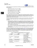
summarizes which FIFO flags will generate interrupts when set. For example a
transmitter FIFO empty flag will result in an interrupt but for a receiver FIFO empty flag a
status bit only is set.
The sticky bits refer to bits I2SGlSts[11:6]. A write of zero is required to clear the setting of
these bits.
Summary of Contents for EP93 Series
Page 28: ...P 6 DS785UM1 Copyright 2007 Cirrus Logic Preface EP93xx User s Guide PP P ...
Page 162: ...5 36 DS785UM1 Copyright 2007 Cirrus Logic System Controller EP93xx User s Guide 55 5 ...
Page 576: ...15 18 DS785UM1 Copyright 2007 Cirrus Logic UART2 EP93xx User s Guide 1515 15 ...
Page 634: ...17 38 DS785UM1 Copyright 2007 Cirrus Logic IrDA EP93xx User s Guide 1717 17 ...
Page 648: ...19 6 DS785UM1 Copyright 2007 Cirrus Logic Watchdog Timer EP93xx User s Guide 1919 19 ...
Page 688: ...21 32 DS785UM1 Copyright 2007 Cirrus Logic I2S Controller EP93xx User s Guide 2121 21 ...
Page 790: ...27 20 DS785UM1 Copyright 2007 Cirrus Logic IDE Interface EP93xx User s Guide 2727 27 ...
Page 808: ...28 18 DS785UM1 Copyright 2007 Cirrus Logic GPIO Interface EP93xx User s Guide 2828 28 ...


