22-2
DS785UM1
Copyright 2007 Cirrus Logic
AC’97 Controller
EP93xx User’s Guide
2
2
2
2
22
and all modem data are at the same sampling rate. If the external codec supported the
following channels: PCM LEFT, PCM RIGHT, MODEM1, PCM CENTRE, PCM L
SURROUND, PCM R SURROUND, PCM LFE, MODEM2 and HSET, then the user would
have to program the transmit side of the controller so that all the audio data was in channel 1,
modem data in channel 2, and the HSET data in channel 3. The controller could also receive
MIC data at a different rate. This data would have to be stored in channel 4. The controller is
designed to allow any slot data to be stored into any channel the user wishes. If the external
codec supports more than 4 sample rates, the user will have to determine which sample rates
to allow.
The controller has four channels, which consist of a transmit FIFO, receive FIFO and their
associated control logic. The control logic can be configured to allow the FIFOs to accept any
data to or from any slot in a frame.
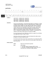
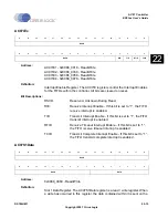
The receive part of each channel is controlled via its AC97RXCR register. This register
controls the following:
•
Which slot data from the received frame is to be stored in the FIFO. The controller will
not store any other slots than those specified in these registers. The user must ensure
that all slot data stored in the FIFO is at the same sampling rate.
•
The length of time before a timeout interrupt is generated.
•
Whether the FIFO is enabled or not.
•
The number of bits in the slot that is captured.
•
Whether the channel is enabled to receive data or not.
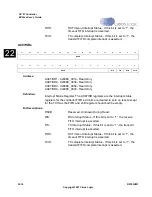
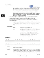
The transmit part of each channel is controlled via its AC97TXCR register. This register
controls the following:
•
Which slot the data in the FIFO is to be transmitted in, the user must ensure that all the
data in the FIFO is intended for slots with the same sampling rate. The data must be
supplied lowest slot number first.
•
Whether the FIFO is enabled or not.
•
The number of bits that need to be appended to the data from the CPU to make the word
20 bits.
•
Whether the channel is enabled to transmit data or not.
•
The transmit channel also supports variable sample rates via the Data Request Disable
Slots from the external codec in slot 1. The data request bits for all audio and modem
data are expected to occur at the same time.
Slot 0 for transmission is determined by the controller depending on the values in the
AC97TXCR register, the data request bits, and the FIFO having valid data to send. If a slot
does not have any data for transmission, the controller will fill the slot with zeros and set the
Tag bits as invalid.
If the external codec does not support the Data Request Disable bits/Variable Rate Extension
the bits will always be “0” meaning a sample rate of 48 kHz. As slots 1 and 2 are always
Summary of Contents for EP93 Series
Page 28: ...P 6 DS785UM1 Copyright 2007 Cirrus Logic Preface EP93xx User s Guide PP P ...
Page 162: ...5 36 DS785UM1 Copyright 2007 Cirrus Logic System Controller EP93xx User s Guide 55 5 ...
Page 576: ...15 18 DS785UM1 Copyright 2007 Cirrus Logic UART2 EP93xx User s Guide 1515 15 ...
Page 634: ...17 38 DS785UM1 Copyright 2007 Cirrus Logic IrDA EP93xx User s Guide 1717 17 ...
Page 648: ...19 6 DS785UM1 Copyright 2007 Cirrus Logic Watchdog Timer EP93xx User s Guide 1919 19 ...
Page 688: ...21 32 DS785UM1 Copyright 2007 Cirrus Logic I2S Controller EP93xx User s Guide 2121 21 ...
Page 790: ...27 20 DS785UM1 Copyright 2007 Cirrus Logic IDE Interface EP93xx User s Guide 2727 27 ...
Page 808: ...28 18 DS785UM1 Copyright 2007 Cirrus Logic GPIO Interface EP93xx User s Guide 2828 28 ...

