22-4
DS785UM1
Copyright 2007 Cirrus Logic
AC’97 Controller
EP93xx User’s Guide
2
2
2
2
22
22.2.1.3 RTIS
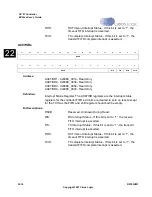
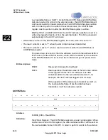
The receive timeout interrupt is asserted when the receive FIFO is not empty and no further
data is received over a number of frames. This number is set by the TOC value in the
AC97RXCR register. The receive timeout interrupt is cleared when the FIFO becomes empty
through reading all the data.
22.2.1.4 TCIS
The transmit complete interrupt is asserted when the transmit FIFO is empty and the parallel
to serial shifter is empty. This indicates that there is no data left in the FIFOs to be sent.
22.2.2 Global Interrupts
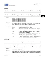
The individual interrupts that are global for the AC97 controller are described below. The
status of these interrupts can be read from the AC97GIS or AC97RGIS registers, and are
masked in the AC97IM register.
22.2.2.1 CODECREADY
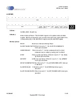
The Codec Ready Interrupt is asserted when the codec has indicated that it is ready by
setting bit15 of Slot0.
This interrupt is cleared by writing a “1” to the appropriate bit of the AC97EOI register.
22.2.2.2 WINT
The Wake-up interrupt is asserted when a wake-up event will trigger the assertion of
SDATAIN while the AC-Link is powered down. The wake-up is caused by the external
codec’s GPIO pins, which have been configured to generate a wake-up event via the codec’s
GPIO pin Wake-up Control register (0x52). An AC-Link wake-up interrupt is defined as a 0-to-
1 transition on SDATAIN when the AC-Link is powered down. The controller knows when the
external codec has been powered down as the SLOT1/2TX registers are monitored to check
for this condition. When the wake up event has been detected on the SDATAIN line, an
interrupt is generated to allow the ARM Core to reactivate the link with either a warm or cold
reset.
This interrupt is cleared by writing a “1” to the appropriate bit of the AC97EOI register.
22.2.2.3 GPIOINT
The receive GPIOINT interrupt is asserted when bit 0 in slot 12 of the incoming SDATAIN is
“1”. This bit indicates that one or more of the bits in slot 12 have changed since the last
frame. It is up to the interrupt service routine to read the AC97S12Data register in order to
clear this interrupt. The external codec’s register (0x54) GPIO pin Status reflects the state of
all of the GPIO pins.
Summary of Contents for EP93 Series
Page 28: ...P 6 DS785UM1 Copyright 2007 Cirrus Logic Preface EP93xx User s Guide PP P ...
Page 162: ...5 36 DS785UM1 Copyright 2007 Cirrus Logic System Controller EP93xx User s Guide 55 5 ...
Page 576: ...15 18 DS785UM1 Copyright 2007 Cirrus Logic UART2 EP93xx User s Guide 1515 15 ...
Page 634: ...17 38 DS785UM1 Copyright 2007 Cirrus Logic IrDA EP93xx User s Guide 1717 17 ...
Page 648: ...19 6 DS785UM1 Copyright 2007 Cirrus Logic Watchdog Timer EP93xx User s Guide 1919 19 ...
Page 688: ...21 32 DS785UM1 Copyright 2007 Cirrus Logic I2S Controller EP93xx User s Guide 2121 21 ...
Page 790: ...27 20 DS785UM1 Copyright 2007 Cirrus Logic IDE Interface EP93xx User s Guide 2727 27 ...
Page 808: ...28 18 DS785UM1 Copyright 2007 Cirrus Logic GPIO Interface EP93xx User s Guide 2828 28 ...


