23-2
DS785UM1
Copyright 2007 Cirrus Logic
Synchronous Serial Port
EP93xx User’s Guide
2
3
2
3
23
23.3 SSP Functionality
The SSP includes a programmable bit rate clock divider and prescaler to generate the serial
output clock SCLKOUT from the input clock SSPCLK. Bit rates are supported to 2MHz and
beyond, subject to choice of frequency for SSPCLK. The maximum bit rate will usually be
determined by peripheral devices.
The SSP operating mode, frame format and size are programmed though the control
registers SSPCR0, SSPCR1.
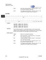
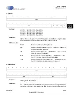
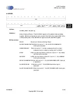
Three individually maskable interrupt outputs, SSPTXINTR, SSPRXINTR and SSPRORINTR
are generated:
•
SSPTXINTR requests servicing of the transmit buffer
•
SSPRXINTR requests servicing of the receive buffer
•
SSPRORINTR indicates an overrun condition in the receive FIFO.
23.4 SSP Pin Multiplex
The SSP pins are multiplexed and may be used for the I
2
S controller instead of SSP by
setting DeviceCfg.I2SonSSP.
23.5 Configuring the SSP
Following reset, the SSP logic is disabled and must be configured when in this state. Control
registers SSPCR0 and SSPCR1 need to be programmed to configure the peripheral as a
master or slave operating under one of the following protocols:
•
Motorola SPI
•
Texas Instruments SSI
•
National Semiconductor.
The bit rate, derived from the external SSPCLK, requires the programming of the clock
prescale register SSPCPSR. The following procedure must be used to initialize the SSP
function:
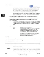
1. Set the enable bit (SSE) in register SSPCR1.
2. Write the other SSP configuration registers: SSPCR0 and SSPCPSR.
3. Clear the enable bit (SSE) in register SSPCR1.
4. Set the enable bit (SSE) in register SSPCR1.
23.5.1 Enabling SSP Operation
You can either prime the transmit FIFO, by writing up to eight 16-bit values when the SSP is
disabled, or allow the transmit FIFO service request to interrupt the CPU. Once enabled,
transmission or reception of data begins on the transmit (SSPTXD) and receive (SSPRXD)
pins.
Summary of Contents for EP93 Series
Page 28: ...P 6 DS785UM1 Copyright 2007 Cirrus Logic Preface EP93xx User s Guide PP P ...
Page 162: ...5 36 DS785UM1 Copyright 2007 Cirrus Logic System Controller EP93xx User s Guide 55 5 ...
Page 576: ...15 18 DS785UM1 Copyright 2007 Cirrus Logic UART2 EP93xx User s Guide 1515 15 ...
Page 634: ...17 38 DS785UM1 Copyright 2007 Cirrus Logic IrDA EP93xx User s Guide 1717 17 ...
Page 648: ...19 6 DS785UM1 Copyright 2007 Cirrus Logic Watchdog Timer EP93xx User s Guide 1919 19 ...
Page 688: ...21 32 DS785UM1 Copyright 2007 Cirrus Logic I2S Controller EP93xx User s Guide 2121 21 ...
Page 790: ...27 20 DS785UM1 Copyright 2007 Cirrus Logic IDE Interface EP93xx User s Guide 2727 27 ...
Page 808: ...28 18 DS785UM1 Copyright 2007 Cirrus Logic GPIO Interface EP93xx User s Guide 2828 28 ...


