26-6
DS785UM1
Copyright 2007 Cirrus Logic
Keypad Interface
EP93xx User’s Guide
2
6
2
6
26
26.2.4 Low Power Mode
The key scanning block also supports a low power wake-up mode. In this mode, a key press
generates a wake up interrupt. The key scan interrupt should be masked. Because the wake
up interrupt is asynchronous, and depends on external keypad lines which may have a large
capacitance value, glitches may occur on the interrupt when transitioning to low power mode.
After transitioning, all clocks to the key scanning circuitry can be shut down. In the low power
mode, all of the column line drivers should be in input mode in a high state due to the pad pull
up resistors. The column inputs are ANDed together to detect any key presses. This signal
directly toggles the interrupt output. The detect condition is not de-bounced.
26.2.5 Three-key Reset
The key scanning circuitry provides a three-key reset output by detecting keys (columns) 2,
4, and 7 activated in row 0. The three-key reset detect is used by the watchdog circuit to
generate a three-key initiated reset to the system.
The output RESET_KEYS_DETECTED goes to the Watchdog block to indicate that a three-
key reset is being requested.
26.3 Registers
Note: Key scan controller registers are intended to be word accessed only. Since the least
significant bytes of the address bus are not decoded, byte and half word accesses are not
allowed and may have unpredictable results.
Register Descriptions
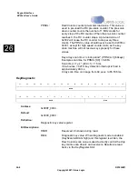
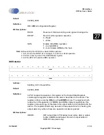
KeyScanInit
Table 26-1. Keypad Interface Register Memory Map
Address
Name
SW locked
Type
Size
Description
0x808F_0000
KeyScanInit
No
Read/Write
24 bits
Key Scan Initialization Register
0x808F_0004
KeyDiagnostic
No
Read/Write
6 bits
Key Scan Diagnostic Register
0x808F_0008
KeyRegister
No
Read Only
16 bits
Key Value Capture Register
31
30
29
28
27
26
25
24
23
22
21
20
19
18
17
16
RSVD
DBNC
15
14
13
12
11
10
9
8
7
6
5
4
3
2
1
0
DIS3KY
DIAG
BACK
T2
NA
PRSCL
Summary of Contents for EP93 Series
Page 28: ...P 6 DS785UM1 Copyright 2007 Cirrus Logic Preface EP93xx User s Guide PP P ...
Page 162: ...5 36 DS785UM1 Copyright 2007 Cirrus Logic System Controller EP93xx User s Guide 55 5 ...
Page 576: ...15 18 DS785UM1 Copyright 2007 Cirrus Logic UART2 EP93xx User s Guide 1515 15 ...
Page 634: ...17 38 DS785UM1 Copyright 2007 Cirrus Logic IrDA EP93xx User s Guide 1717 17 ...
Page 648: ...19 6 DS785UM1 Copyright 2007 Cirrus Logic Watchdog Timer EP93xx User s Guide 1919 19 ...
Page 688: ...21 32 DS785UM1 Copyright 2007 Cirrus Logic I2S Controller EP93xx User s Guide 2121 21 ...
Page 790: ...27 20 DS785UM1 Copyright 2007 Cirrus Logic IDE Interface EP93xx User s Guide 2727 27 ...
Page 808: ...28 18 DS785UM1 Copyright 2007 Cirrus Logic GPIO Interface EP93xx User s Guide 2828 28 ...

