19-2
DS785UM1
Copyright 2007 Cirrus Logic
Watchdog Timer
EP93xx User’s Guide
1
9
1
9
19
19.1.1 Watchdog Activation
The Watchdog circuitry may be disabled via software for test purposes on products that do
not wish to use a Watchdog timer by writing 0xAA55 to the Watchdog register. The Watchdog
may also be re-enabled via software by writing 0xAAAA to the Watchdog register.
The Watchdog circuitry may be disabled via hardware on products that do not need to use a
Watchdog timer, by applying an external pull down on the CSn[1]
(HW_WATCHDOG_DISABLEn) signal during reset. This will allow the block to detect the
presence of the resistor during the bus reset (HRESETn low) and disable the counter. During
reset, the chip will disable the output driver and provide a weak pull-up resistor on this pad.
19.1.2 Clocking Requirements
The WATCHDOG_CLK for stepping the counter in the Watchdog has a frequency that is
nominally 256 Hz, for generating a 250 ms time-out and a 250 ms reset pulse duration.
19.1.3 Reset Requirements
The Watchdog block has the following four reset inputs:
•
HRESETn: This is the AHB bus reset signal from the Syscon block, which includes a
software reset.
•
USR_RESETn: This is the external user reset input, and its status is kept in register
Watchdog[2].
•
PWR_RESETn: This is the power-on-reset input for resetting everything including reset
status bits. The power-on-reset is generated by a combination of the external PRSTn pin
and the on chip voltage monitor/power up detector.
•
RESET_KEYS_DETECTED: The Watchdog will time out if the three-key reset signal
from the key scanning controller is activated. This input disables the ability to reset the
Watchdog. If the Watchdog is hardware or software disabled, detection of the three-key
reset will over-ride the Watchdog counter disable and cause the circuit to time out and
generate the WATCHDOG_RESETn output anyway. It behaves as a USR_RESETn
signal.
19.1.4 Watchdog Status
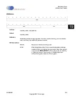
The Watchdog timer register can be read to determine the cause of a reset. The register
contains user reset status (external reset on RSTOn), three-key reset status from the key
scan controller, and Watchdog reset status bits (reset caused by WATCHDOG_RESETn).
The state of these bits determines if the reset condition was the result of a user reset, a three-
key reset, a power on reset, or a watch dog time-out. The status of these bits can only be
cleared by a power on reset (internal chip voltage detect power on signal PWR_RESETn). An
additional 7-bit status register is provided in the Watchdog module as WDSTAT. This status
value is held through all resets but power on reset. The system can be reset by a three-key
reset, a user reset, or a Watchdog reset without losing the contents of this register.
Summary of Contents for EP93 Series
Page 28: ...P 6 DS785UM1 Copyright 2007 Cirrus Logic Preface EP93xx User s Guide PP P ...
Page 162: ...5 36 DS785UM1 Copyright 2007 Cirrus Logic System Controller EP93xx User s Guide 55 5 ...
Page 576: ...15 18 DS785UM1 Copyright 2007 Cirrus Logic UART2 EP93xx User s Guide 1515 15 ...
Page 634: ...17 38 DS785UM1 Copyright 2007 Cirrus Logic IrDA EP93xx User s Guide 1717 17 ...
Page 648: ...19 6 DS785UM1 Copyright 2007 Cirrus Logic Watchdog Timer EP93xx User s Guide 1919 19 ...
Page 688: ...21 32 DS785UM1 Copyright 2007 Cirrus Logic I2S Controller EP93xx User s Guide 2121 21 ...
Page 790: ...27 20 DS785UM1 Copyright 2007 Cirrus Logic IDE Interface EP93xx User s Guide 2727 27 ...
Page 808: ...28 18 DS785UM1 Copyright 2007 Cirrus Logic GPIO Interface EP93xx User s Guide 2828 28 ...


