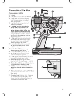
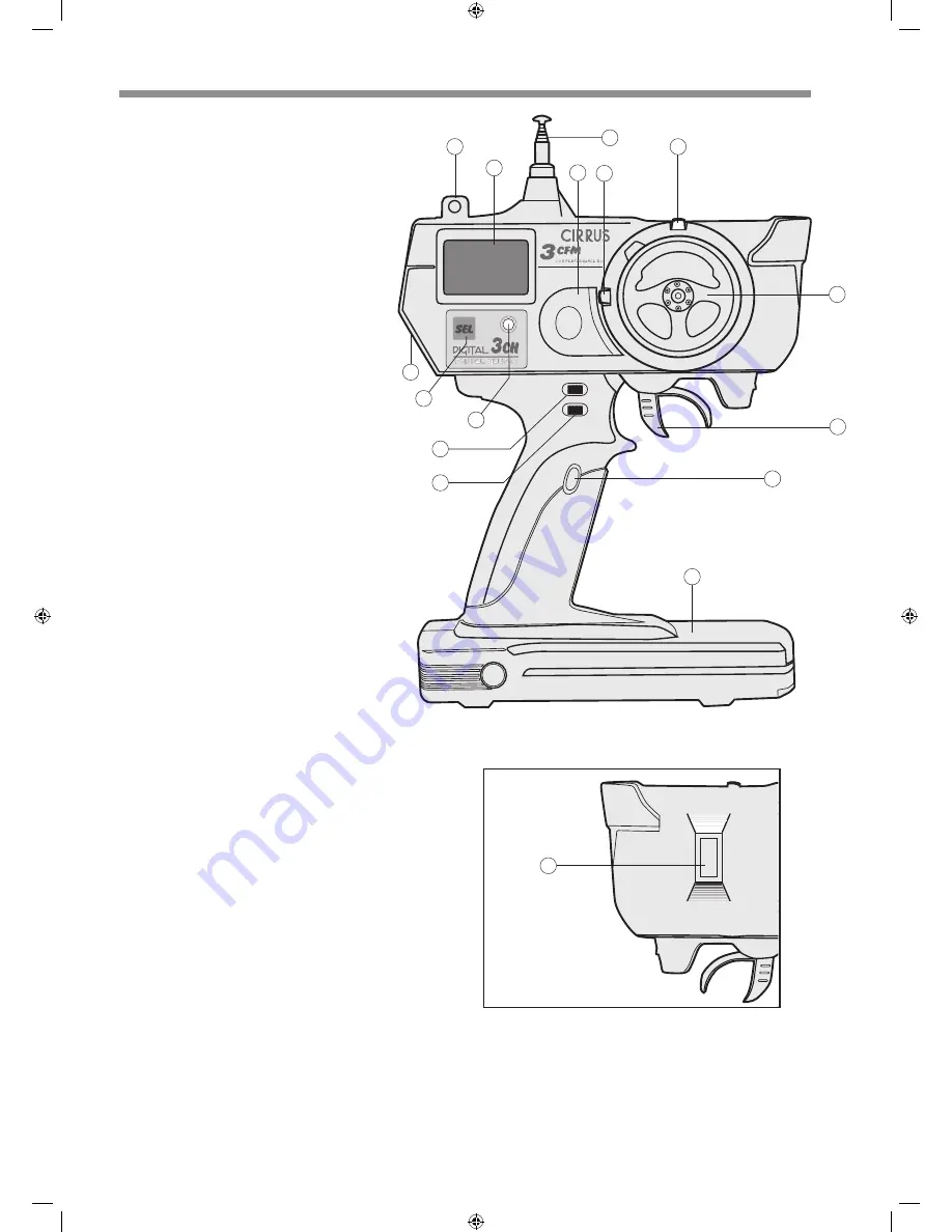
background image

1.   Antenna 

2.   Power Switch:

 Turns your transmitter ON & OFF. 

3.   Charging Jack:

 For onboard charging when 

using rechargeable batteries (not supplied). 
See page 5 For details. 

4.   Strap Base:

 For the securing of an optional 

safety strap (not supplied). 

5.   LCD Display:

 Displays all menu screens for 

function updates, power level indicator, etc. 

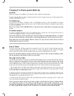
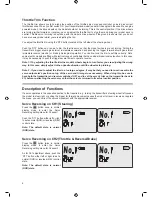
Note: Once you have finished making any 
function adjustments (using the ‘Function Select’ 
and ‘DT1’ buttons), wait approximately 6 seconds 
without making any further adjustments to set the 
change. As this happens you will see the screen 
will return to its normal display mode, indicating 
that the change is saved. 

6.   LED Indicator:

 Illuminates when the transmitter 

is switched on, blinks when transmitter displays 
low power. Works in conjunction with audible 
beeps when making function changes.

7.   Function Select Button:

 Allows you to select 

the menu screens that let you make function 
updates. 

8.   Function Button DT1:

 Operates steering trim 

and is main function changing button. 

9.   Function Button DT2:

 Operates throttle trim. 

10. Steering Wheel:

 Proportionally operates the 

model’s left and right steering control. 

11. Throttle Trigger:

 Controls the speed of the model and 

movement forward and backward, or brake. 

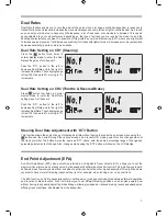
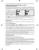
12. Function Button DT3:

 Allows quick Dual Rate 

adjustment for Ch1 (Steering). See page 7 For details. 

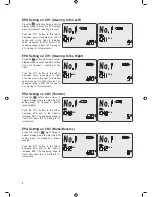
13. Function Button DT4:

 Allows quick EPA adjustment for 

Ch2 (Reverse/Brake). See page 9 For details. 
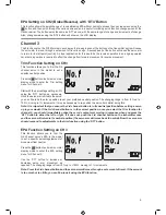
14. Ch3 Button:

 Used to operate a third function, like 

reversing on an engine-powered car. See page 9 For 
details. 

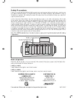
15. Battery Compartment:

 Houses batteries (AA/UM3) that 

power the transmitter. Also includes holder for a pair of 
spare crystals.

16. Transmitter Crystal:

 Crystals on differing frequencies 

allow multiple models to operate together without 
interference and are matched in pairs with a similar 

crystal fitted to the receiver in the model.

Nomenclature / Handling

Transmitter: 3CFM 

1

4

2

12

15

14

10

D I S P L A Y

CONTROL SYSTEM

S E L

5

3

16

8

9

11

13

3

6

7

Summary of Contents for 3CFM

Page 1: ...D I S P L AY L INSTRUCTION MANUAL High performance 3 CHANNEL Computer R C ...

Page 2: ...s actual frequency printed on it and details of whether it is for transmitter Tx or receiver Rx Crystals are matched in pairs e g Tx 27 145MHz and Rx 27 145MHz Transmitter and receiver crystals matched pairs can be purchased separately and changed if interference is detected someone operating on the same frequency as you As a rule it is always good to carry at least one spare pair of crystals to a...

Page 3: ... make function updates 8 Function Button DT1 Operates steering trim and is main function changing button 9 Function Button DT2 Operates throttle trim 10 Steering Wheel Proportionally operates the model s left and right steering control 11 Throttle Trigger Controls the speed of the model and movement forward and backward or brake 12 Function Button DT3 Allows quick Dual Rate adjustment for Ch1 Stee...

Page 4: ... At the same time the LCD screen will illuminate If the LED fails to light no beeps are heard and the LCD display fails to illuminate double check that you have installed the batteries the correct way round in the transmitter and try again If the LED still fails to light and no audible beeps are heard check that the batteries you have installed are fully charged Note The Cirrus 3CFM transmitter is...

Page 5: ...re that ensures that you have effective control over your model Steering Trim Function The steering trim allows you to fine tune the position of the steering servo so as to give correct steering response Place your model on a flat level surface and drive it slowly forwards without touching the steering wheel If your model drives in a straight line no adjustment is necessary If your model pulls eit...

Page 6: ...ng the throttle trim the model s wheels begin to turn faster you are adjusting the wrong way In this case simply adjust in the opposite direction until the wheels stop turning Note 2 If you need to adjust the trim to a too large a degree it may be that you need to re set re centre the servo output arm s position on top of the servo and trim again as necessary When doing this be sure to have both t...

Page 7: ...ht to increase Dual Rate The changing range is from 100 down to 5 moving in 1 increments Steering Dual Rate Adjustment with DT3 Button This function allows the quick change of steering dual rate without having to access the on screen menu using the button and then scroll through the various screens and is useful for making quick function changes when at the track or similar The button works the sa...

Page 8: ...right of centre and to the right to increase servo movement to right of centre The changing range is from 120 down to 5 moving in 1 increments EPA Setting on CH2 Throttle Press the button seven times in normal display mode to enter the EPA setting menu for Channel 2 throttle accelleration Push the DT1 button to the left to decrease EPA and to the right to increase EPA The changing range is from 12...

Page 9: ...the servo arm is fitted to the servo you can fine tune the arm s position to set your preferred neutral position The changing range is from 0 up to 100 moving in 1 increments It may be necessary to re position the servo horn whilst doing this Note It is important that you ensure the 3rd channel button is in its neutral position before setting a servo up in your model If the 3rd channel button is i...

Page 10: ...ect the model memory number you require There are 10 model memories or modes numbered 0 through 9 Once you have selected the appropriate model memory mode you can adjust it as required using the and DT1 buttons as detailed previously The new selection will set after 8 seconds In this way you can preset parameters for up to 10 models in advance and simply select the appropriate model memory when yo...

Page 11: ... water and or snow will cause them to fail with resultant loss of control of your model Should any type of moisture enter any part of your radio system stop using it immediately and return it to the specified service centre for inspection repair Do not operate your model within 1 6Km 1 Mile of another sight where radio control activity commonly occurs Interference from other radio systems operatin...

Page 12: ...eriodically check the receiver servos and battery connectors to be sure that all are firmly joined If a connector is not fully inserted vibration can cause it to work loose while your model is operating resulting in a loss of control The receiver aerial may seem overlong but its length is critical DO NOT cut it If the length of the receiver aerial is altered the receiver will be adversely affected...

Page 13: ... 6 0V Torque 4 8V 13Kg cm 149oz in Torque 6 0V 11Kg cm 153oz in Dimensions 40 6x19 8x37 8mm 1 6x0 78x0 48in Weight 55g 1 93oz Servo CS601 BB High Torque Ballraced Standard Servo Speed 0 20 sec 60 4 8V 0 16 sec 60 6 0V Torque 4 8V 5 5Kg cm 75oz in Torque 6 0V 6 5Kg cm 102oz in Dimensions 40 6x19 8x37 8mm 1 6x0 78x1 48in Weight 55g 1 93oz Servo CS703 MG Metal Geared Ballraced Servo Speed 0 22 sec 60...

Page 14: ... Move ON OFF switch to ON position ON OFF switch is defective Replace ON OFF switch No control of model Weak batteries in transmitter Replace recharge batteries Weak batteries in model Replace recharge batteries Radio interference Relocate or change crystals Limited radio range Weak batteries in transmitter Replace recharge batteries Weak batteries in model Replace recharge batteries Transmitter a...

Page 15: ...They are neither authorised nor equipped to perform warranty work on Cirrus products When requesting warranty service please observe the following Crash damage will not be covered under warranty nor will a dropped transmitter be covered Do not request warranty service for crash damaged or dropped product Always return the whole system transmitter receiver switch and battery box if supplied Include...

Reviews: