51-20
Page 8
All
EFFECTIVITY:
C I R R U S
A I R P L A N E M A I N T E N A N C E M A N U A L
M O D E L S R 2 0
01 May 2012
(a)
Acquire necessary tools, equipment, and supplies.
(b)
Remove surface protection from section of repair area.
(c)
Solvent clean repair area.
Note:
The thickness of one ply is 0.008 - 0.010 inch (0.203 - 0.254 mm). To verify,
or if no value is found in the ply lay-up tables, determine ply count by divid-
ing measured laminate thickness by 0.009 inch (0.229 mm).
(d)
Using a micrometer, measure the thickness of undamaged, unpainted laminate in an area
adjacent to the repair area.
(e)
For partially penetrated damage:
1
Using a micrometer, measure the thickness of damaged laminate in the repair area.
2
Determine number of damaged plies by subtracting thickness of damaged laminate
from undamaged laminate.
(f)
Reference the ply lay-up tables in the Airframe Zone Diagrams, to verify the number of
plies.
(4)
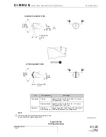
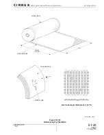
The glass-fabric used for repair on this airplane is Hexcel 7781. This fabric is considered a bal-
anced cloth because approximately 50% of the fibers run parallel to warp, and approximately
50% run perpendicular to warp. Fibers that run parallel to the selvage edge have a fiber orienta-
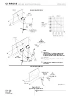
tion of 0°. The warp clock, located on each of the Airframe Zone Diagrams, is used to determine
ply orientation by indicating how the – and + angled plies are defined. The warp clock is always
viewed from the outside of the fuselage, or the tool surface, looking in.
Generally, the +0° axis is parallel to the ground and/or centerline of the fuselage. For example,
the main spar runs perpendicular to the 0° axis. The 90º axis is always perpendicular to the 0º
axis. The 45º axis is located by moving clockwise from 0º to 90º.
Once ply orientation is determined, it is permissible to mark the warp axis on the repair fabric
with a permanent marker.
Description
P/N or Spec.
Supplier
Purpose
Micrometer
-
Any Source
Measurement.


