95-01-01
Page 56
Serials 1423 & subs w/o Perspective after SB2X-95-18
EFFECTIVITY:
C I R R U S
C O M P O N E N T M A I N T E N A N C E M A N U A L - C A P S
M O D E L S R 2 0
4 May 2015
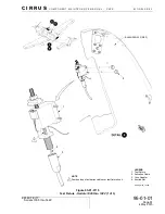
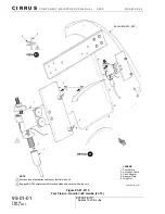
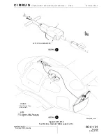
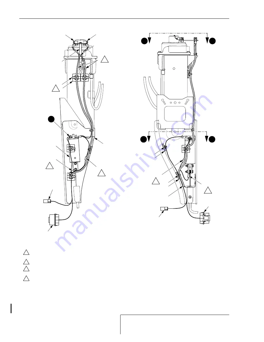
Figure 95-01-0112
Rocket Assembly Wiring - Serials 1423 & subs w/o Perspective after SB2X-95-18 (2 of 4)
2
3
2 PLC'S
2
7
6
TR1453
(POSITIVE)
TR1455
(NEGATIVE)
1
4
P1046
P1046
4
LEGEND
1. Wiring Harness
2. Cable Tie
3. Cable Anchor
4. Igniter Switch
5. Rocket Shield
6. Standoff
7. Sleeving
SR20_CM95_3619B
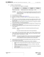
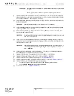
Install anchors and cable ties to prepared surface on side of launch tube using adhesive.
Wrap wires with tape as required to ensure security hold under cable ties.
NOTE
Secure R2700 and wires to anchor at back of rocket shield with cable tie.
Install TR2705 as shown with hardware provided. Orient linkage as shown and position
ring lug downward and towards front of aircraft.
Place sleeving on each wire. Position sleeving as shown and secure to standoff using
cable tie. Secure sleeving at ends with cable ties to prevent fraying.
TR2705
R2700
5
R2700
TR2705
FORWARD-SIDE VIEW
LOOKING AFT
1
LH-SIDE VIEW
LOOKING RIGHT
P2701
P2701
2
3
2
3
1
4
3
2
C1
C1
D
3
2
3
2
C2
C2
Serials 1423 & subs w/o Perspective after SB2X-95-18.


