background image

79-30

Page 8

Serials 1602, 1644, 1663 & subs

EFFECTIVITY:

C I R R U S


A I R P L A N E   M A I N T E N A N C E   M A N U A L

M O D E L  S R 2 2

15 Apr 2007

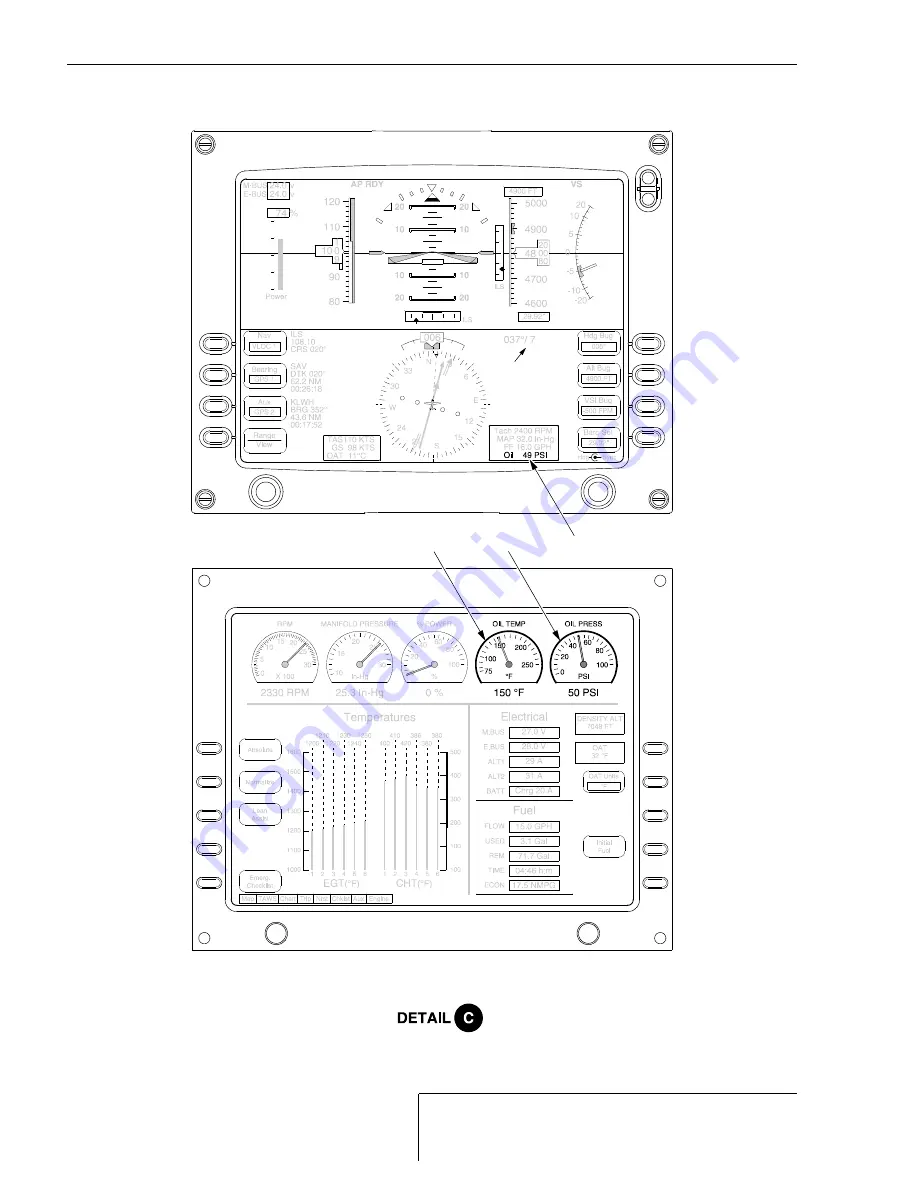
Figure 79-301

Oil Pressure and Oil Temperature Indication - Serials 1602, 1644, 1663 & subs (Sheet 2 of 2)

SR22_MM79_2232


LEGEND

1. Oil Pressure Gage
2. Oil Temperature Gage

1,2

2

1

Summary of Contents for SR22

Page 1: ...ed through the 5 amp ENGINE INST circuit breaker on the Essential Bus Serials 1602 1644 1663 subs Oil pressure is displayed in the upper right corner of the MFD as both a simulated pressure gage and as text The simulated pressure gage receives a signal from a pressure sen sor mounted at the aft end of the engine below the oil cooler via the Data Acquisition Unit DAU The sim ulated pressure gage sw...

Page 2: ...1 60 d Disconnect electrical connector from gage e Remove screws and washers securing gage to instrument panel Remove gage from air plane 2 Installation Oil Pressure Temperature Gage a Position gage to instrument panel and secure with screws and washers b Connect electrical connector to gage c Install MFD Refer to 31 60 d Reset ENGINE INST circuit breaker e Perform Operational Test Oil Pressure Te...

Page 3: ...re is displayed on the MFD screen 1 Operational Test Oil Pressure Temperature Gage a Set BAT1 and AVIONICS switches to ON positions b On MFD when PRESS ANY BEZEL KEY TO CONTINUE is displayed press any key c If Engine Monitoring is selected press Fuel Done to enter Map page d Rotate left knob to select Engine page e Verify oil temperature needle indicates bottom of scale f Verify oil pressure needl...

Page 4: ...603 thru 1643 1645 thru 1662 Pull ENGINE INST circuit breaker c Serials 1602 1644 1663 subs Pull ANNUN ENGINE INST circuit breaker d Remove engine cowling Refer to 71 10 e Disconnect electrical connector from sensor f Remove sensor from engine 2 Installation Oil Pressure Sensor a Position sensor to engine and install b Connect electrical connector to sensor c Install engine cowling Refer to 71 10 ...

Page 5: ...ove engine cowling Refer to 71 10 e Disconnect electrical lead from sensor f Remove safety wire securing sensor to engine g Remove sensor and washer from engine Discard washer 2 Installation Oil Temperature Sensor a Acquire necessary tools equipment and supplies b Position new washer and sensor to engine and install c Connect electrical lead to sensor d Safety wire sensor to oil cooler Refer to 20...

Page 6: ... oil pressure temperature warning light is integrated into the annunciator assembly mounted top cen ter above the flight instruments The oil light will illuminate if the oil temperature exceeds 240 F 116 C or if the oil pressure is less than 10 psi 68 9 kPa For maintenance practices pertinent to the annunciator assembly see Indicating and Recording Refer to 31 50 ...

Page 7: ...ssure and Oil Temperature Indication Sheet 1 of 2 SR22_MM79_1474C OIL COOLER REF LEGEND 1 Oil Pressure Gage 2 Oil Temperature Gage 3 Screw 4 Washer 5 Connector 6 Oil Pressure Sensor 7 Oil Temperature Sensor 8 Wire Harness Terminal Ring 9 Nut 9 4 8 9 6 5 7 4 5 1 2 4 3 Serials 0002 thru 1601 1603 thru 1643 1645 thru 1662 15 Apr 2007 ...

Page 8: ...R R U S A I R P L A N E M A I N T E N A N C E M A N U A L M O D E L S R 2 2 15 Apr 2007 Figure 79 301 Oil Pressure and Oil Temperature Indication Serials 1602 1644 1663 subs Sheet 2 of 2 SR22_MM79_2232 LEGEND 1 Oil Pressure Gage 2 Oil Temperature Gage 1 2 2 1 ...

Reviews: