background image

10

5.

  Select Internet Protocol Version 4 (TCP/IPv4) and click on prop-

        erties

6.

  In the internet Protocol Version 4 (TCP/IPv4) properties window, 

        change from default “Obtain an IP address automatically” to 
        “Use the following IP address:” Enter “192.168.0.101” as the 
        IP address and “255.255.255.000” as the Subnet mask.

        Note: If an IP address conflict occurs because IP address    

       192.168.0.101 is already assigned to another Net 

        work Adapter, the user can try any other IP address between 

        192.168.0.102 and 192.168.0.249.

7.

  Once the IP address is entered, click OK. Connect the PC to 

        the Controller using the provided Ethernet cable by inserting 
        one end of the cable in the controller’s Ethernet port and the 
        other one in the “USB-to-Network Adapter”. Power on the    
 

controller. To check that the PC to controller connection was  


successful, ensure the icon of the “ASIX AX88179 USB 3.0 to 

        Gigabit Ethernet Adapter” in the Control Panel matches the 
        image below. Network Connection can be renamed using the 
        right mouse click menu.

8.

  A more in depth check of the PC-to-controller communication 

       connection can be done by running a “ping command” in Com-
       mand Prompt as seen in the image below. To ping the controller, 
       type “ping 192.168.0.250” and press enter. Ping certifies 
       IP-level connectivity to another TCP/IP device. If you receive 
       Ping statistics for IP address 192.168.0.250 (controller IP ad-
       dress) the communication connection between the PC and 
       controller was successful.

Summary of Contents for ZEUS 008Z

Page 1: ...IMAGE ACQUISITION TREATMENT PLANNING DOSE DELIVERY USER GUIDE ZEUS MRgRT Motion Management QA Phantom Model 008Z 900 Asbury Ave Norfolk Virginia 23513 USA Tel 757 855 2765 WWW CIRSINC COM ...

Page 2: ...dure 6 Zeus Cables and Connections 7 ViewRay MRIdian System Accessories 8 Setup notes for Dynamic Phantoms with controller connecting to a PC using an Ethernet connection 9 CIRS Motion Control Software 11 Zeus Specifications 12 Warranty 13 Notes 14 Table of Contents ...

Page 3: ...background gel which fills the void between the organs Besides imaging all organs except for the lungs offer ion chamber dosimetry cavities which allow for completing an entire QA process from imaging to planning to verification of dose delivered Zeus is designed as a single unit with a piezo actuator fixed permanently to a base plate on which the MRI body snaps This allows for quick setup re mova...

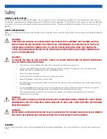
Page 4: ...ed check with a qualified electrician Do not remove ground prong Do not install or use this product near water or when you are wet Operate the product securely on a stable surface Set up the product in a protected location where no one can step on or trip over the power cord and the power cord can not be damaged It is recommended that the customer install an AC surge arrestor in the AC outlet to w...

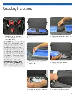
Page 5: ...ntains potential dam aged goods The sensor displays a red arrow when applied before shipping If the container receives a shock exceeding 25 G force the sensor display arrows will change to blue If the sensor has been activated and is blue a claim may need to be filed with the carrier If activated take extra care in inspecting the compo nents as they are unpacked assembled and tested Note If there ...

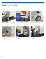
Page 6: ...image above 2 Place rod into phantom body and screw the rod and actuator together 3 Insert ion chamber into each cavity hole Moving target 4 Insert ion chamber into each cavity hole Liver 5 Insert ion chamber into each cavity hole Kidney 6 Insert ion chamber into each cavity hole Spine ...

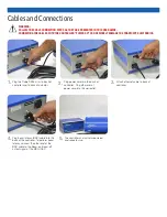
Page 7: ...ller and actuator powered and ready for use 4 Plug beam latency BNC cable into the back of the controller To perform beam latency connect the other end of the BNC cable to the Beam on Beam off output signal of the MRI LINAC Cables and Connections WARNING FOLLOW THE CABLE CONNECTION STEPS AS THEY ARE PRESENTED IN THIS USER GUIDE CONNECTING THE CABLES WITH THE CONTROLLER POWER ON CAN SERIOUSLY DAMAG...

Page 8: ...ntroller box and the male connector to the 40ft cable 4 Pull the 40ft cable from another side of the RF closet and connect it to the back of the actuator ViewRay MRIdian System Accessories WARNING FOLLOW THE CABLE CONNECTION STEPS AS THEY ARE PRESENTED IN THIS USER GUIDE CONNECTING THE CABLES WITH THE CONTROLLER POWER ON CAN SERIOUSLY DAMAGE THE PHANTOM S ELECTRONICS LOW PASS RF FILTER COIL SUPPOR...

Page 9: ...ovided USB drive or download the zipped folder from the CIRS website Unzip to a known location and follow instructions from Instructions pdf document 2 Follow the on screen steps and acknowledge all the mes sages related to driver s installation Once the driver installa tion is finished plug the USB to Network Adapter into your PC s USB port and acknowledge the Windows installa tion message Exit t...

Page 10: ...rting one end of the cable in the controller s Ethernet port and the other one in the USB to Network Adapter Power on the controller To check that the PC to controller connection was successful ensure the icon of the ASIX AX88179 USB 3 0 to Gigabit Ethernet Adapter in the Control Panel matches the image below Network Connection can be renamed using the right mouse click menu 8 A more in depth chec...

Page 11: ...s usually located under the current user in the Application Data folder A Windows OS search function can be used to find the log file Searching hidden files and folders should be enabled The log file provides a record of the motion history of the device and can be used as objective evidence that proper QA was performed CIRS Motion Control Software SOFTWARE USER MANUAL SOFTWARE UPGRADES CIRS Motion...

Page 12: ...ables kit Ethernet cable adapter 1 User s guide 2 Carry Case OVERALL DIMENSIONS 67 cm x 32 cm x 20 cm OVERALL WEIGHT 12 kg 26 5 lbs AMPLITUDE IS 25 mm AMPLITUDE AP LR 3 5 mm MOTION ACCURACY 0 2 mm linear motion MOTION ACCURACY 0 25o rotation motion CYCLE TIME 1 adjusted based on amplitude WAVEFORMS sin t 1 2cos4 t 1 2cos6 t sawtooth sharkfin built in custom through import OVERALL DIMENSIONS 25 6 c...

Page 13: ...NS If you are not satisfied with your purchase for any reason please contact Customer Service or your local distributor prior to returning the product Visit https www cirsinc com distributors to find your local distributor Call 800 617 1177 email rma cirsinc com or fax an RMA request form to 757 857 0523 CIRS staff will attempt to remedy the issue via phone or email as soon as possible If unable t...

Page 14: ...14 NOTES ...

Page 15: ...15 NOTES ...

Page 16: ... notice Publication 008Z UG 082521 Computerized Imaging Reference Systems Inc has been certified by UL DQS Inc to ISO 13485 2016 Certificate Registration No 10000905 MP2016 COMPUTERIZED IMAGING REFERENCE SYSTEMS INC 900 Asbury Ave Norfolk Virginia 23513 USA Toll Free 800 617 1177 Tel 757 855 2765 Fax 757 857 0523 Email admin cirsinc com www cirsinc com Technical Assistance 1 800 617 1177 ...

Reviews: