background image

VCC-12CL1M 


Rev. 900-795-35-00 

©2016 CIS Corporation. All rights reserved. 


Camera  Link  I/F 

12M  Pixels  CMOS  B/W  Camera 

VCC-12CL1M


Product Specifications 

& Operational Manual 


CIS Corporation 

English 

Summary of Contents for VCC-12CL1M

Page 1: ...VCC 12CL1M Rev 900 795 35 00 2016 CIS Corporation All rights reserved Camera Link I F 12M Pixels CMOS B W Camera VCC 12CL1M Product Specifications Operational Manual CIS Corporation English ...

Page 2: ...guration Mode 22fps Factory settings 13 8 2 Vertical Synchronous Signals Timing Medium Configuration Mode 22fps 13 8 3 Horizontal Synchronous Signals Timing Full 8Tap10Bit Configuration Mode 43fps 14 8 4 Vertical Synchronous Signals Timing Full 8Tap10Bit Configuration Mode 43fps 14 8 5 Horizontal Synchronous Signals Timing 10Tap Configuration Mode 54fps 15 8 6 Vertical Synchronous Signals Timing 1...

Page 3: ... or cold places operating temperature 5 to 4 5 Close to generators of powerful electromagnetic radiation such as radio or TV transmitters Places subject to fluorescent light reflections Places subject to unstable flickering etc lighting conditions Places subject to strong vibration Remove dust or dirt on the surface of the lens with a blower Do not apply excessive force or static electricity that ...

Page 4: ...ull Configuration output Features Global shutter CMOS sensor is utilized Camera Link Medium Configuration Full Configuration 10Tap8Bit and 8Tap10bit Configuration are supported Fixed trigger shutter mode and pulse width trigger shutter mode are operable Full frame rates and video output format are as follows Binarization Shading correction Free Software CIS control panel software for evaluation pu...

Page 5: ...tal clock 416 Vertical frequency 54 84Hz Scanning lines 3156 3 Sync System Internal Sync System 4 Video Output Medium Configuration Full Configuration factory settings 10Tap8Bit Configuration 8Tap10Bit Configuration 5 Resolution 3000 TV Lines 6 Output Format Camera Link output 8bit 10bit 12bit Fixed to 8bit at 10Tap mode B W output 7 Sensitivity F5 6 400lx at Shutter speed 1 43s OFF Gain 0dB and F...

Page 6: ... Specification 1 Video output data Effective Video Output 4000 H 3000 V At full frame scan mode 2 Sync Signal output LVAL Pin No 6 12pins Circular Connector LVTTL Output FVAL Pin No 7 DVAL Pin No 10 EXPOSURE Pin No 9 LVAL Camera Link output LVDS FVAL DVAL SP Exposure pulse 3 Trigger Input Polarity Positive Negative selectable Polarity is selectable at Address 11 Pulse Width Approx 14HD min Approx ...

Page 7: ...ty characteristic the lens characteristic and the illuminant characteristic are excluded 5 4 Video Output Format 1 Medium Configuration Mode 22fps 2 Full 8Tap10Bit Configuration Mode 43fps Factory settings D D D D 3000 Line 4000 Pixel 1 2 3 4 D D D D D D D D 3000 Line 4000 Pixel 1 2 3 4 5 6 7 8 ...

Page 8: ... Configuration Mode 0 1 22s OFF 1 43s OFF 1 54s OFF 1 1 60s 1 60s 1 60s 2 1 100s 1 100s 1 100s 3 1 120s 1 120s 1 120s 4 1 150s 1 150s 1 150s 5 1 200s 1 200s 1 200s 6 1 250s 1 250s 1 250s 7 1 500s 1 500s 1 500s 8 1 1000s 1 1000s 1 1000s 9 1 2000s 1 2000s 1 2000s 10 1 5000s 1 5000s 1 5000s 11 1 10000s 1 10000s 1 10000s 12 1 18000s 1 20000s 1 15000s 13 1 35000s 1 35000s 1 25000s 14 1 35000s 1 70000s ...

Page 9: ... max value 3000 42 1ms Full 8Tap10Bit Configuration Mode Shutter Speed 7 222us 1HD x setting value min value 2 14 4us max value 3000 21 7ms 10Tap Configuration Mode Shutter Speed 5 778us 1HD x setting value min value 2 11 6us max value 3000 17 3ms The minimum value at Fixed Trigger Shutter Mode is set to 14 and the shutter speed at that time comes to the fastest value of the address 2 ex Min expos...

Page 10: ...s Cursor display ON OFF 32 0 OFF 1 ON Cursor X Address 33 0 3999 0 3999 Horizontal 4000 pixels Cursor Y Address 35 0 2999 0 2999 Vertical 3000 lines Partial Scan Start Position 1 40 0 2998 Partial Scan Start Position 2 41 0 2998 Partial Scan Start Position 3 42 0 2998 Partial Scan Start Position 4 43 0 2998 Set the data of Address 15 to 1 Odd setting is not acceptable Partial Scan Effective lines ...

Page 11: ...ghts reserved 11 7 External Connector Pin Assignment 7 1 12 pins Circular Connector HR10 10R 12PA HIROSE equivalent Pin No 1 GND 2 Power Input DC 12V 3 GND 4 GND 5 GND 6 LVAL Output 7 FVAL Output 8 GND 9 EXPOSURE Output 10 DVAL Output 11 Trigger Input 12 GND ...

Page 12: ...s 2 CL Select when a non PoCL supported frame grabber is used When changing the selection of the switch please confirm that the power of the power supply source is turned OFF always Changing the switch at the powering up might cause malfunction to the camera Pin No Pin No Pin No Pin No 1 NC 12V PoCL 14 GND 1 NC 12V PoCL 14 GND 2 X0 15 X0 2 Y0 15 Y0 3 X1 16 X1 3 Y1 16 Y1 4 X2 17 X2 4 Y2 17 Y2 5 Xcl...

Page 13: ... 1H 1010 CLK Camera Link Port B Camera Link CLK 72MHz Camera Link Port A 1 3 5 7 2 4 6 8 3993 3995 3997 3999 3994 3996 3998 4000 1 2 Video Out 3 9 9 9 4 0 0 0 3 4 3 9 9 7 3 9 9 8 4Tap Medium Configuration Output 22 6fps モード FVAL Out 1Frame 3156H 44 2ms Effective Line DVAL Out LVAL Out Effective Line V Blanking 156H Exposure Time 1 SP Out Exposure Out 3 0 0 0 3 0 0 0 1 1 1H 14 028us Video Out Effe...

Page 14: ... Port A 1 3 2 4 3993 3995 3994 3996 1 2 Video Out 3 9 9 9 4 0 0 0 3 4 3 9 9 7 3 9 9 8 Camera Link Port H Camera Link Port G Camera Link Port F Camera Link Port E 5 7 6 8 3997 3999 3998 4000 5 6 7 8 3 9 9 5 3 9 9 6 3 9 9 3 3 9 9 4 8Tap Full Configuration Output 43 9fps モード FVAL Out 1Frame 3156H 22 7ms Effective Line 3000H Effective Line DVAL Out LVAL Out Effective Line V Blanking 156H Exposure Tim...

Page 15: ...eo Out 3 9 9 9 4 0 0 0 3 4 3 9 9 7 3 9 9 8 Camera Link Port H Camera Link Port G Camera Link Port F Camera Link Port E 5 7 6 8 3995 3997 3996 3998 5 6 7 8 3 9 9 5 3 9 9 6 3 9 9 3 3 9 9 4 Camera Link Port J Camera Link Port I 9 10 3999 4000 3 9 9 1 3 9 9 2 9 1 0 10Tap Configuration Output 54 8fps モード FVAL Out 1Frame 3156H 18 2ms Effective Line 3000H Effective Line LVAL Out Effective Line V Blankin...

Page 16: ...prox 1 30000s 10Tap Configuration Mode Approx 1 34000s Triggers cannot be accepted during the Exposure Time and Outputting images Refer to A in the drawing below The exposure time is Shutter setting value 9 fixed value x 1HD When you switch between Full Frame Scan Mode and Partial Scan Mode or when you change Partial setting the first output image is subject to be unstable Input the first as dummy...

Page 17: ...here is no upper limitation but noises such as dark noises shadings may be noticeable at long time exposure Triggers cannot be accepted during the Exposure Time and Outputting images When you switch between Full Frame Scan Mode and Partial Scan Mode or when you change Partial setting the first output image is subject to be unstable Input the first as dummy trigger and use the trigger from the seco...

Page 18: ...automatically inside a camera Set a parameter of binarization threshold value address 25 to 512d Barcode Based on the brightness distribution of edge areas in image the threshold value is calculated automatically inside a camera The object which has a lot of edges such as barcode and character can be binarized with less influences of the fluctuation in flat areas and or backgrounds Refer to the be...

Page 19: ...ta in advance the correction is performed by setting ON a shading correction address 26 10 1 Calculating shading correction data When the object with uniform levels such as a pattern box is imaged on the whole screen and a shading correction data calculation start address 27 is set ON the correction data is calculated inside a camera automatically and saved Start the shading correction data settin...

Page 20: ...Corporation All rights reserved 20 11 Partial Scan Mode Maximum 4 partial areas can be set by serial commands Example 3 partial areas to be set V Blanking Fixed to 156H Partial Area 1 Partial Area 2 Partial Area 3 Total line count per frame ...

Page 21: ...e Medium Configuration Mode 14 028us Full 8Tap10Bit Configuration Mode 7 222us 10Tap Configuration Mode 5 778us Setting Examples Effective Lines Entire frame lines Frame Rate Entire frame lines Medium Configuration Mode Full 8Tap10Bit Configuration Mode 10Tap Configuration Mode 2 Min 2 H 158H 451fps 876fps 1095fps Vertical VGA equivalent 480 H 636H 112fps 217fps 272fps Vertical XGA equivalent 768 ...

Page 22: ...command parameter and CR 0x0d The change and acquisition of setting parameters can be done by issuing commands from PC Command Parameter 1 Parameter 2 Function GU Address None Obtain setting information SU Address Data Change camera settings As for the address and the data please refer to 5 Function settings 3 How to set a command Input a command in capital letters Separate between a command and a...

Page 23: ...t engine org 13 Factory Settings Function Address Data Gain 1 0 0dB Shutter 2 0 1 43s OFF Trigger Shutter Mode 4 0 Normal Shutter Mode Trigger OFF Trigger Polarity 11 0 Positive Trigger Input 12 0 Camera Link CC1 Input Output Data Selection 13 0 8bit Output Partial Scan Mode 15 0 Full Frame Scan Mode Vertical Flip 20 0 OFF Horizontal Flip 21 0 OFF Gamma Correction 23 0 OFF Binarization 24 0 OFF Sh...

Page 24: ...VCC 12CL1M Rev 900 795 35 00 2016 CIS Corporation All rights reserved 24 14 CMOS Optical Axis Accuracy ...

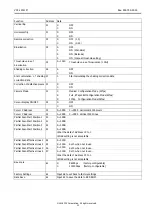
Page 25: ...VCC 12CL1M Rev 900 795 35 00 2016 CIS Corporation All rights reserved 25 15 Dimensions ...

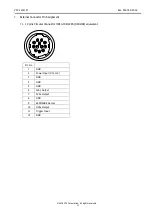
Page 26: ...VCC 12CL1M Rev 900 795 35 00 2016 CIS Corporation All rights reserved 26 ...

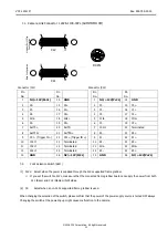
Page 27: ...VCC 12CL1M Rev 900 795 35 00 2016 CIS Corporation All rights reserved 27 ...

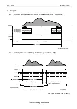
Page 28: ...VCC 12CL1M Rev 900 795 35 00 2016 CIS Corporation All rights reserved 28 ...

Page 29: ...used by use contrary to the instructions in this product specification operation manual In case damage or losses are caused by malfunction or other problems resulting from use of equipment or software that is not specified In case damage or losses are caused by repair or modification conducted by the customer or any unauthorized third party such as an unauthorized service representative Expenses w...

Page 30: ...0 19 Ordering Information Model Name Connector Position Baud Rate bps VCC 12CL1M T1 TOP 115200 VCC 12CL1M T9 TOP 9600 VCC 12CL1M B1 BOTTOM 115200 VCC 12CL1M B9 BOTTOM 9600 VCC 12CL1M L1 LEFT 115200 VCC 12CL1M L9 LEFT 9600 VCC 12CL1M R1 RIGHT 115200 VCC 12CL1M R9 RIGHT 9600 ...

Reviews: