VCC-5CL1R
Rev. 905-0022-02
©2015 CIS Corporation. All rights reserved.
9
◇
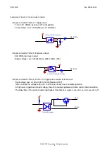
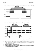
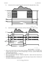
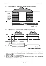
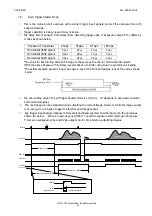
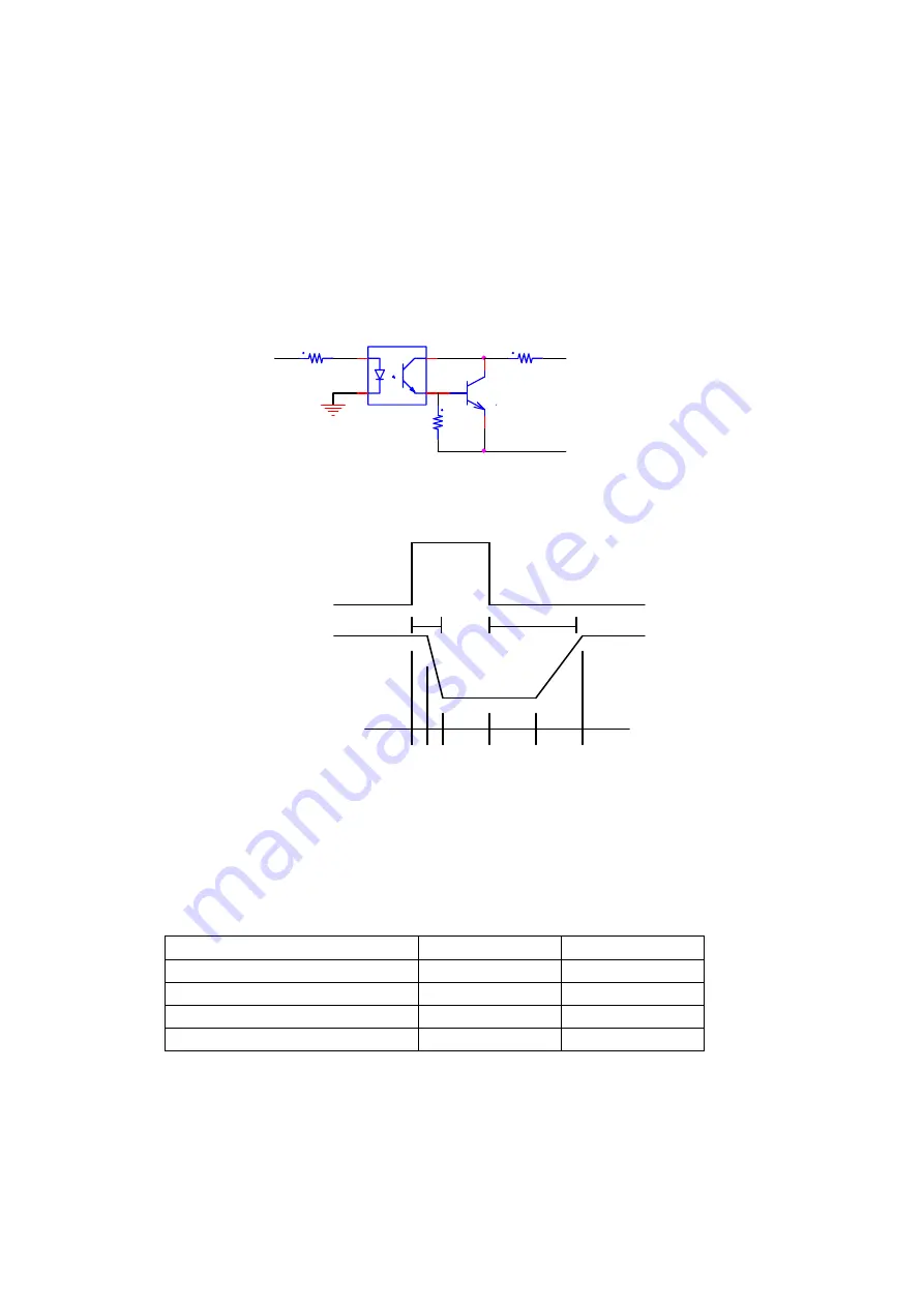
12pins connector Pin No 7, Pin No 12
:
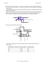
Exposure photo coupler isolated output. (Transistor NPN output)
・
Use it as an open collector output. The sink current flows into a camera should not exceed 50mA
(Maximum 25V).
・
Due to the delay of the photo coupler input/output transmission, several
μ
s delay against the actual sensor
exposure time would occur.
・
When a pull up resistor is used, the delay time is subject to change due to the pull up voltage, the pull up
resistor and the connecting circuit of the user’s circuit. Please set a value get an appropriate waveform.
※
For your reference,
“
exposure output
”
of 12pins connector Pin No.7 is a pulse with no delay.
TLP291SE (Toshiba)
22
B
E
C
2SC3052 (ISAHAY A ELECTRONICS)
(Ref) input / output waveform of photo coupler
t
_
d
(
d
e
l
a
y
_
t
i
m
e
)
OFF
t
_
f
(
f
a
l
l
t
i
m
e
)
t
_
r
(
r
i
s
e
t
i
m
e
)
ON
t
_
s
(
s
t
o
r
a
g
e
t
i
m
e
)
出力波形
入力波形
t _ o f f
t _ o n
・
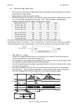
Please refer to the Table below for the output voltage with the combination of pull up voltage and
pull up register
Pull up voltage
(
V
)
at the user side Pull up resistor
(
Ω
)
Output voltage(V)
24 4.7k
1.1
12 4.7k
0.4
12 2.7k
0.8
5 1.2k
0.7
7 pin
12 pin
Input ware form
Output ware form


