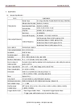
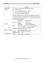
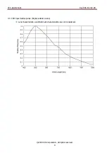
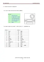
background image

VCC-G22U21ACL  

Rev.900-612-32-00


©2009 CIS Corporation. All rights reserved. 


UXGA B/W Camera 

49MHz Pixel Clock Camera Link


VCC-G22U21ACL 


Product Specification 

& Operational Manual 


CIS Corporation 


English

Summary of Contents for VISION:mini VCC-G22U21ACL

Page 1: ...VCC G22U21ACL Rev 900 612 32 00 2009 CIS Corporation All rights reserved UXGA B W Camera 49MHz Pixel Clock Camera Link VCC G22U21ACL Product Specification Operational Manual CIS Corporation English...

Page 2: ...rnal Connector Pin Assignment 12 6 1 6 pins Circular Connector HR10 7R 6PA HIROSE 12 6 2 26pins camera Link connector 12226 1100 00 PL SUMITOMO 3M 12 7 Timing Chart 13 7 1 Horizontal Synchronous Signa...

Page 3: ...old places operating temperature 5 to 45 Close to generators of powerful electromagnetic radiation such as radio or TV transmitters Places subject to fluorescent light reflections Places subject to un...

Page 4: ...r supply voltage may cause noises on the video signals z The rising time of camera power supply voltage shall be less than 10V Max 60ms Please avoid noises like chattering when rising In case of abnor...

Page 5: ...ull Frame Scan Mode entire pixels can be read out within approx 1 20s Interface of G22U21ACL complies with camera link standard Key Features Camera settings can be changed via serial communications Se...

Page 6: ...e Resolution 1000 TV lines Resolving power 8bit 10bit Sensitivity F5 6 400 lx Shutter 1 20s Gain 0dB Minimum illumination F1 4 1 0 lx Shutter 1 20s Gain 12dB Dust or stains in optical system No dust o...

Page 7: ...two conditions 1 this device may not cause harmful interference and 2 this device must accept any interference received including interference that may cause undesired operation Durability Vibration A...

Page 8: ...tput LVDS DVAL output LVDS HD VD input None Trigger input Polarity POSI NEGA Selectable Min Trigger Pulse width Over 1 HD Camera Link input LVDS CC1 input Camera Link connector TTL Input Refer to the...

Page 9: ...VCC G22U21ACL Rev 900 612 32 00 2009 CIS Corporation All rights reserved 9 4 3 CCD Spectral Response Representative value Lens characteristics and illuminant characteristics are not considered...

Page 10: ...de Off 1 Fixed Trigger Shutter Mode Shutter speed can be set with address 002 2 Pulse Width Trigger Shutter Mode Shutter speed can be set with trigger pulse width Scan Mode 005 0 Full Frame Scan Mode...

Page 11: ...e 1 CLK Synchronous Mode Data Save 015 Input 083 to save address 000 014 into EEP ROM Note Please note the followings when using trigger shutter mode Re triggering at H Synchronous Mode shall be after...

Page 12: ...nk connector 12226 1100 00 PL SUMITOMO 3M Pin No 1 Power IN 12V 2 Trigger IN TTL Level 3 RS 232C RXD option 4 RS 232C TXD option 5 Do not connect 6 GND Pin No Pin No 1 GND 14 GND 2 X0 15 X0 3 X1 16 X1...

Page 13: ...VAL Signal Output Video Signal Output 1600CLK 14CLK 14CLK Active Area DVAL Signal Output 7 2 Vertical Synchronous Signal Timing 7 2 1 Normal Shutter Mode Trigger Shutter Mode OFF Recommended number of...

Page 14: ...Area 9H 9H Trigger Input LVAL output FVAL output DVAL output SP output Discharge signal Read Out signal Video Signal Exposure Time Re Trigger Input Cancell Area 7 2 2 Trigger Shutter Mode CLK Synchron...

Page 15: ...ndividual camera R Read mode Please refer to the address table of 5 Function Settings 000 255 0 Dh W Write mode C Camera mode Camera No shall consist of 6 bytes of characters numeric strings Send the...

Page 16: ...mmy data at read control mode CR Be sure to input CR to confirm the end of the command 10ms should be waited to send the next command after receiving the response from the camera when changing the mod...

Page 17: ...datum plane 14 5 29 6 0 3 6 0 3 6 0 3 6 0 3 10 0 3 10 0 3 29 M2 M3 M2 Datum Plane The center of effective pixels shall be within 0 6 to the center of lens mount Inclination of effective pixels to dat...

Page 18: ...41 28 12 29 DC IN 12 2 M2 Depth 3 4 5 999 482 00 00 3 4 5 12 20 3 M3 Depth 3 Product Name Label Position 4 M2 Depth 3 C Mount 23 7 M3 Size 22 M2 Size C Mount screws comply with ANSI ASME B1 1 1 32UN...

Page 19: ...malfunction or non function of the equipment we shall be exempted from responsibility for such damages In case damage or losses are caused by failure to observe the information contained in the instr...

Page 20: ...would like us to investigate on the cause and repair please contact your distributors you purchased from to consult and coordinate Control SW Sample software for camera control RS 232C can be downloa...

Reviews: