
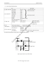


VCC-GC20V41CL
Rev.900-721-32-00
©2011 CIS Corporation. All rights reserved.
17
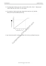
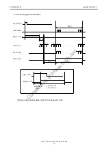
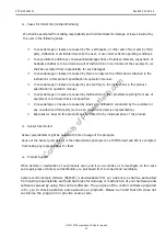
LVAL Output
10 H
FVAL Output
DVAL Output
n H
· · ·
Video Output
· · · · · · ·
Exposure Time
2 H
· · · · · · ·
· · · · · · ·
2 H
n H (Max.)
Video Output
s s+1
s+n
-1
s+n
s+n
-2
s+n
-3
s+n
-1
s+n
s+n
-2
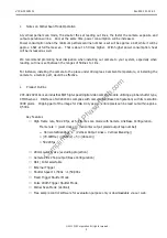
480
· · ·
FVAL Output
Partial scan (vertical 1/2) n: 240H
Manual partial scan n: any
· At full frame scan
· At vertical partial scan
· · ·
· · ·
0
1
2
119 120
359 360
479
478
2 H
Partial scan (vertical 1/2) s: 120H
Manual partial scan s: any
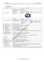
480
(The max vertical partial
scan output lines)
n = 400
The set vertical partial scan
output lines
0 ~ 80
Vertical partial scan
Starting position
Setting range
s = 90 (invalid)
vertical partial scan
starting position
Set value
s = 80 (with limitation)
vertical partial scan
starting position
0
80
90
479
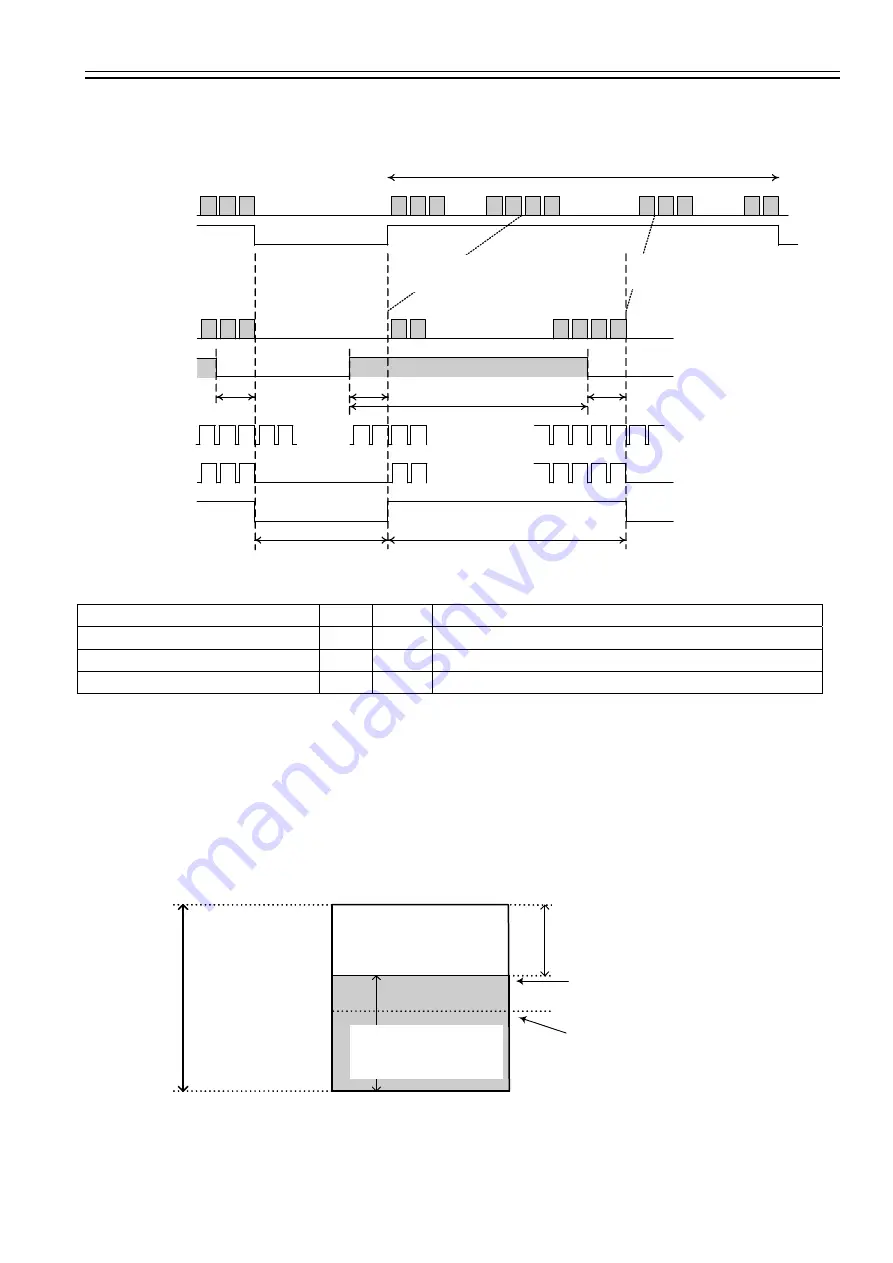
9.
Partial Scan Mode
・
Vertical Partial Scan
s:
Vertical partial scan starting position (address 016
&
017)
n:
Vertical partial scan output lines (address 019
&
020)
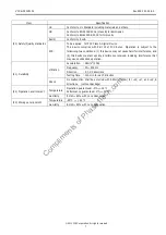
Scan Mode (address:005)
s
n
Vertical Sync. Frequency (Hz)
0:Full frame scan mode
0
480
502.29
1:Partial scan mode (Vertical 1/2)
120
240
984.49
2:Manual partial scan mode
Any
any
79.99MHz /((Vertical partial scan output lines +10)×(325))
・
The max value of vertical partial scan starting position is limited with the formula below since vertical partial scan output
line has priority.
The max value of vertical partial scan starting position
=480(The max value of vertical partial scan output line) –
Vertical partial scan output lines
(Ex.) When 400 is set as vertical partial scan output lines, the max value of vertical partial scan starting position will be
480-400 = 80.
If vertical partial scan starting position is set to 90 with this time, vertical partial scan output line has priority so that vertical
partial scan starting position shall be limited to 80.
※
At manual partial scan mode, manual shutter value to be set shall meet the following conditions.
The set manual shutter lines
≦
Vertical partial scan output lines
If the condition above is not met, shutter lines to be set will be the same number as vertical partial scan output lines.
Compliments
of
Phase1tech.com


