- 3 -
OPERATION
INTERFACING FOR OPENING
See the eFAST MORTICE panic exit device manual
Diagram 1: example of button/switch connection to lock power supply.
Diagram 2: example of lock connection to intercom
The electric current produced by some intercoms can be high, keeping the panic exit device open even after the opening
button has been released.
It is advisable to interface the intercom with a repeater relay and connect the motor as shown in diagram 3 if necessary.
Diagram 3: example of lock connection to an intercom using a repeater relay
INTERFACING FOR PANIC EXIT DEVICE STATUS
See the eFAST MORTICE panic exit device manual
Connect devices with a maximum current absorption of 0.5A and a maximum voltage of 60V. CISA declines all responsibility
for the compliance of third-party devices used
It is possible to connect the 12V
lights (see the accessories) directly to the lock power supply. Respect the polarity (+/-) of the lights/LEDs.
A repeater relay (item 1.07022.20.0) is needed to control locks, electric strike coils or 230V devices.
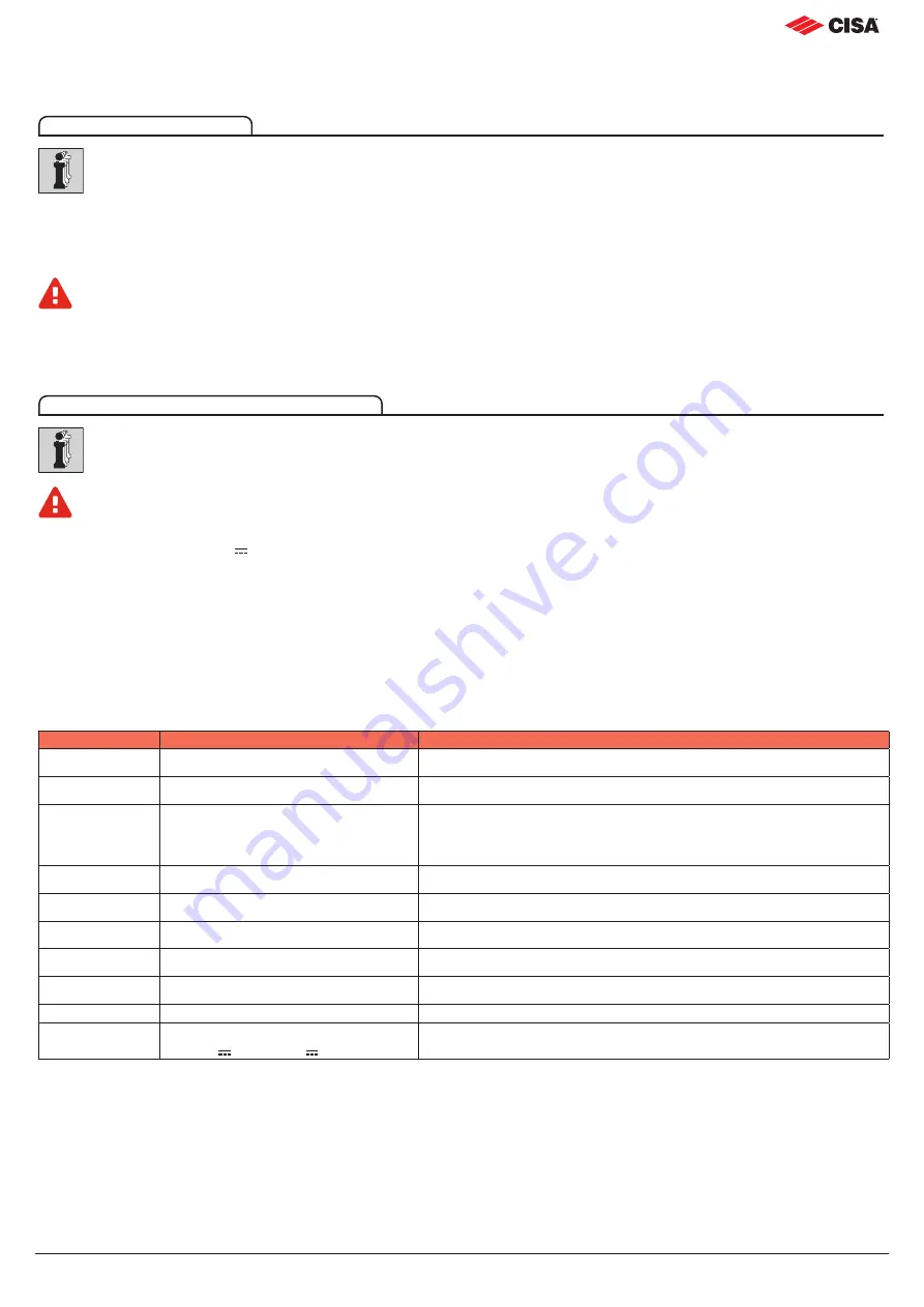
DIAGNOSTICS
When installation is complete, check operation and any sound signals.
Sound signal are emitted to indicate errors and malfunctions.
Status
Action
Sound/visual signals (*)
On
System correctly started up
2 short sound signals - Flashing green LED inside the motor
Mechanical actions
Engaging/withdrawing deadbolts
No sound signal
Motor actions
Complete opening
(lat deadbolts)
2 short sound signals
Motor actions
Reverting to starting position
No sound signal
Motor actions
Motor movement
Flashing yellow LED inside the motor
Motor actions
Setting hold open mode
Yellow LED on inside the motor
Error
Rod sensor blocked
1 long sound signal - Red LED on inside the motor
Error
Motor in safety timeout
2 long sound signals - Red LED on inside the motor
Error
Motor blocked mechanically
3 long sound signals - Red LED on inside the motor
Error
Incorrect power supply voltage
Vin <11V or Vin >16V
4 long sound signals - Red LED on inside the motor
(*) = Sound signals can be disabled through the PC.


